
Polishing device for metal part

A polishing device and a technology for metal parts, which are applied in the direction of used abrasive processing devices, metal processing equipment, abrasives, etc., can solve the problems of low polishing efficiency of metal parts, inability to meet high-efficiency production, and long polishing time, so as to improve the overall The effect of polishing uniformity, improving the overall polishing efficiency, and improving the stability of use

Inactive Publication Date: 2018-07-10
合肥盛强数控设备股份有限公司
View PDF9 Cites 2 Cited by
  • Summary
  • Abstract
  • Description
  • Claims
  • Application Information

AI Technical Summary

Problems solved by technology

The polishing devices currently used all use static polishing. During the polishing process, there will be many places that have not been polished, and this kind of polishing will cause some places to be polished, but some places are not polished, resulting in The overall polishing is uneven, and the polishing time is long, and the polishing efficiency of the overall metal parts is low
[0003] In summary, the existing polishing devices for metal parts still have great defects in structure and design, and cannot meet people's needs for efficient production

Method used


Image

  • Polishing device for metal part
  • Polishing device for metal part
  • Polishing device for metal part

Examples


Embodiment 1

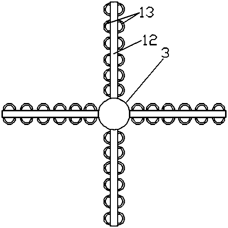
[0022] Embodiment 1: There are four hanging rods 12 in the hanging rod group.

Embodiment 2

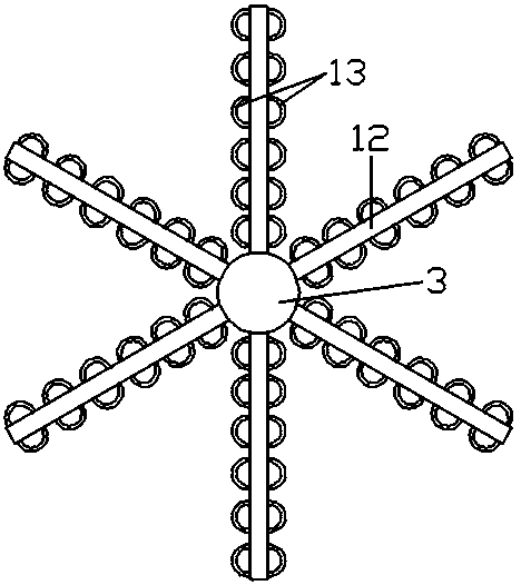
[0023] Embodiment 2: There are six hanging rods 12 in the hanging rod group.

[0024] The principle of operation of the polishing device for metal parts is as follows:

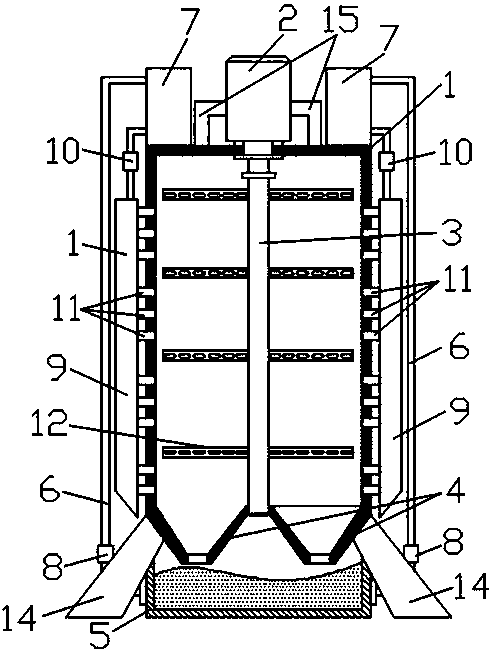
[0025] First of all, the operator can hang the metal parts on the hanging rod 12 through the hook, and then during the sandblasting process, the electric drive reduction motor 2 runs, so that the rotating shaft 3 can rotate to drive the hanging rod group to rotate, and the hanging rod group The hanging metal parts can be rotated by themselves, so that they can be polished at 360 degrees without dead angles, which can greatly improve the uniformity of polishing, shorten the overall polishing time, and improve polishing efficiency.


PUM


Abstract

The invention relates to a polishing device for a metal part. The polishing device comprises a polishing chamber, a reducing motor is perpendicularly arranged at the top end of the polishing chamber,the output end of the reducing motor is connected with a rotating shaft, the rotating shaft is perpendicularly provided with a plurality of hanging rod groups along the length direction, tapered sanddischarge openings are arranged at the lower end of the polishing chamber and positioned at two sides of the rotating shaft, a sand box is arranged at the lower end of the polishing chamber and positioned at the lower parts of the tapered sand discharging openings, two sides of the sand box are connected with transfer boxes through pipelines, the transfer boxes are fixedly arranged at two sides ofthe reducing motor at the upper end of the polishing chamber, the pipelines are fixedly provided with sand pumps, one sides of the transfer boxes are connected with sandblasting pipelines through pipelines, every transfer box and sandblasting pipeline connecting pipeline is provided with a pressure pump, the sandblasting pipelines are perpendicularly arranged at two sides of the polishing chamber, a plurality of sandblasting openings are perpendicularly arranged at one sides, facing the sidewall of the polishing chamber, of every sandblasting pipeline, and the plurality of sandblasting openings go through the sidewall of the polishing chamber, and extend into the polishing chamber. The polishing device for the metal part improves the overall polishing uniformity, shortens the polishing time and improves the overall polishing efficiency.

Description

technical field [0001] The invention relates to the technical field of polishing devices, in particular to a polishing device for metal parts. Background technique [0002] With the continuous development of society, the mechanical technician industry has developed rapidly. A complete product needs to go through multiple processing procedures, among which polishing is an important part. Usually the product will be polished before being sprayed or painted. Polishing treatment can remove rust and oxide film on the surface of metal products, which is convenient for subsequent spraying or painting. The polishing devices currently used all adopt static state polishing. During the polishing process, there will be many places that have not been polished, and this kind of polishing will cause some places to be polished and many places to be not polished, resulting in The overall polishing is uneven, and the polishing time is long, and the polishing efficiency of the overall metal...

Claims


Application Information

Patent Timeline
Patent Type & Authority Applications(China)
IPC IPC(8): B24C3/02B24C9/00
CPCB24C3/02B24C9/00
Inventor 阮睿阮守聪
Owner 合肥盛强数控设备股份有限公司
Learn More