
Structure for cutting off hair in fluid and floor drain using structure

A fluid and hair technology, applied in the field of household kitchen and bathroom building drainage devices, can solve the problems of high cost, unreachable reamer, difficult production process, etc., and achieve the effects of easy replacement, simple use, and simple structure design.

Pending Publication Date: 2018-07-10
陆全东
View PDF1 Cites 7 Cited by
  • Summary
  • Abstract
  • Description
  • Claims
  • Application Information

AI Technical Summary

Problems solved by technology

The application number is: 201410582086.3, and the name is: an improved floor drain. A technical solution is recorded as "the blade of the base intersects with the blade of the cover, and when the base is covered by the cover, the blade of the base and the cover The floor drain is tangent to the plate blade. It is mentioned in the application that by turning the cover plate, the blade on the cover plate and the blade on the base work together to cut off the hair. There are three problems in this. 1. The blade must be a protruding part. It can also be seen from the drawings that the two tangent blades lead to a very large gap in the middle. If the flow of the floor drain is not particularly large, the hair must flow down the side wall of the floor drain, and then along the gap between the adjacent two blades. The gap slides down without being cut by the blade; 2. Even if it is not left along the side wall, the blade is set tangent to the blade. If the blade is too close, it will be easily damaged, and the hair is very small. If the gap is large, there will be continuous cutting. Situation; 3. Even if it is cut off, there is no limit to the length after cutting, there will still be a large section of hair, which will still cause blockage
[0004] Another idea is to install an electric motor in the floor drain to drive the reamer to cut off the hair. First, the cost is high, second, the production process is difficult, and third, hair is an easy-to-tangle material. Unable to achieve the desired effect

Method used


Image

  • Structure for cutting off hair in fluid and floor drain using structure
  • Structure for cutting off hair in fluid and floor drain using structure
  • Structure for cutting off hair in fluid and floor drain using structure

Examples


Embodiment 1

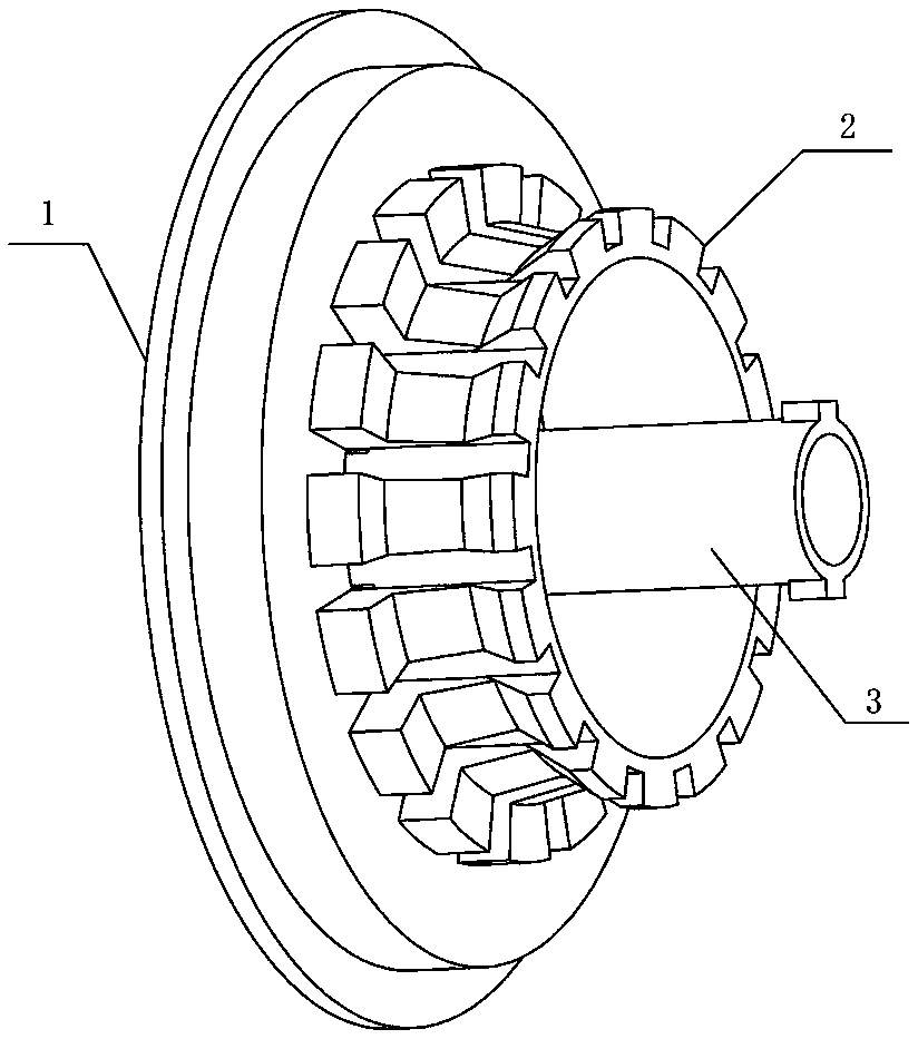
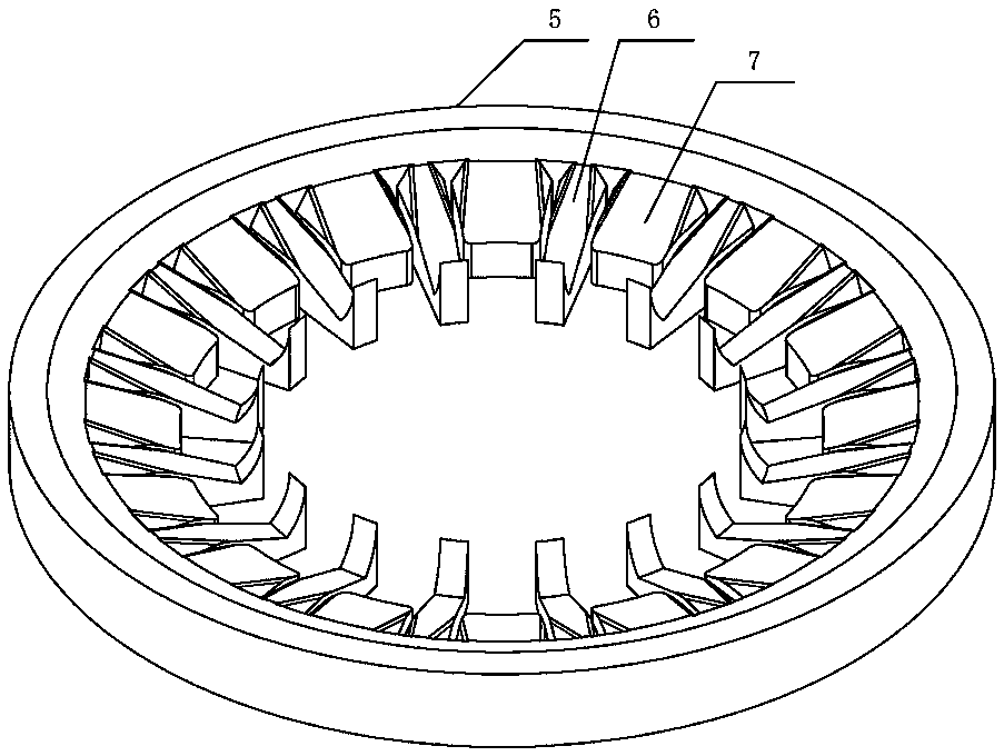
[0054] The lower part of the upper gland 1 is radially provided with 32 movable cutters 4, and the adjacent fixed cutters 6, the pad knife block 7 and the lower end of the spacer block 2 are surrounded by 16 drains 14, and water flows into the sewer from the drains 14, and the hair Since the diversion body 8 changes the flow direction of the water flow, the straight up and down water flow becomes a horizontal swirl;

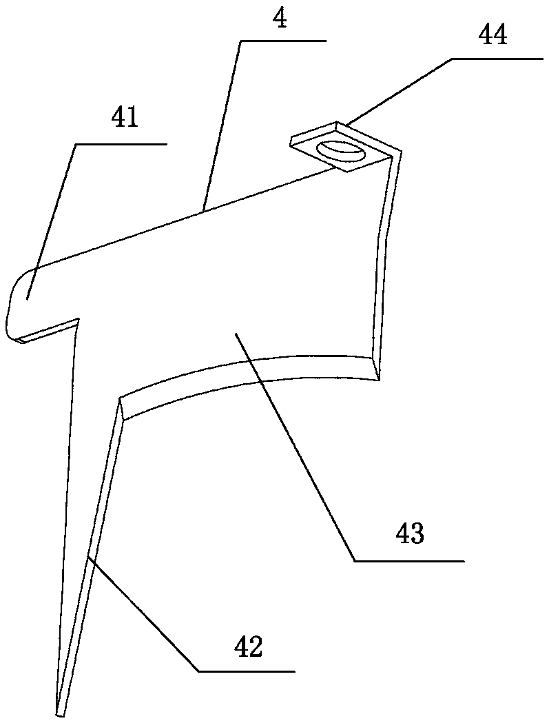
[0055] as attached Figure 9 , the floor drain is in the initial state, a gap is set between the tip of the movable cutter 4 blade portion 43 and the front end of the fixed cutter 6, the size of the gap is preferably 5 mm, the hair in the water flow falls horizontally on the fixed cutter 6 through this gap, and cannot pass through the drain 14. Due to the scouring of the water flow, the hair is collected at the junction of the cutting part and the anti-falling cutter head;

[0056] as attached Figure 10 , the upper gland 1 is applied with an external force, th...


PUM


Abstract

The invention relates to a structure for cutting off hair in fluid and a floor drain using the structure. The structure comprises an upper press cover and an outer casing, wherein the upper press cover is connected with the outer casing in a mode of doing intermittent reciprocating motion along the axial direction of the outer casing; a gap is arranged at a combining part of the upper press coverand the outer casing; movable cutters spaced for a preset distance are arranged at the lower part of the upper press cover; a fixed cuter body is arranged in the outer casing; fixed cutters matched with the movable cutters for completing the shearing action are arranged on the fixed cutter body; a flow guide body is also arranged in the outer casing; the preset quantity of flow guide blades inclined towards the same direction are arranged at the inner wall of the flow guide body. For the floor drain using the structure, the lower part of the outer casing is connected with a sewer pipe; the width of each separation block is 2 to 4 times the space between the adjacent separation blocks. The structure for cutting off the hair in fluid provided by the invention has the advantages that the design is simple and compact; the use is simple; the cutting-up work on hair and foreign matters can be completed by pressing the upper press cover in the bath process or after the bath is finished; the cut-off hair can be flushed away along with the water flow in a harmless way.

Description

technical field [0001] The invention relates to the technical field of drainage devices for household kitchen and bathroom buildings, in particular to a structure for cutting hair in fluid and a floor drain using the structure. Background technique [0002] In the place where the sewer or other pipes transport water, hair or other fine fibers will be mixed in, and these hairs or fine fibers are soft and erratic in the water flow, and their accumulation will inevitably cause stagnation. It is very difficult to cut the hair to a harmless length in the fluid. The current main technical method is to filter the hair out, but this is time-consuming and laborious; especially in the bathroom, there will be hair that falls off every time you take a bath, although the amount is not enough Large, but if it is not cleaned in time, it will cause blockage after a period of accumulation. Almost everyone has the experience of cleaning bathroom and toilet floor drains, which is very unhygien...

Claims


Application Information

Patent Timeline
Patent Type & Authority Applications(China)
IPC IPC(8): E03F5/04B26B19/06
CPCE03F5/0407E03F5/041B26B19/06E03F2005/0416Y02A30/60
Inventor 颜慕依陆全东
Owner 陆全东
Learn More