Concrete silo top plate structure and construction method thereof

A concrete and roof technology, applied in building types, buildings, large-capacity bulk material storages, etc., can solve the problems of long period of erection and dismantling of formwork systems, high working surface height, and high safety risks, so as to reduce construction costs, The effect of saving costs and avoiding security risks

Active Publication Date: 2018-07-10
THE THIRD CONSTR OF CHINA CONSTR FIRST GROUP +1
View PDF7 Cites 1 Cited by
  • Summary
  • Abstract
  • Description
  • Claims
  • Application Information

AI Technical Summary

Problems solved by technology

[0003] The purpose of the present invention is to provide a concrete silo roof structure and its construction method, to solve the problem of high working surface height, high safety risk, large construction investment, long construction period and difficult High cost, technical problems of formwork system erection and long dismantling cycle

Method used


Image

  • Concrete silo top plate structure and construction method thereof
  • Concrete silo top plate structure and construction method thereof
  • Concrete silo top plate structure and construction method thereof

Examples


Embodiment 1

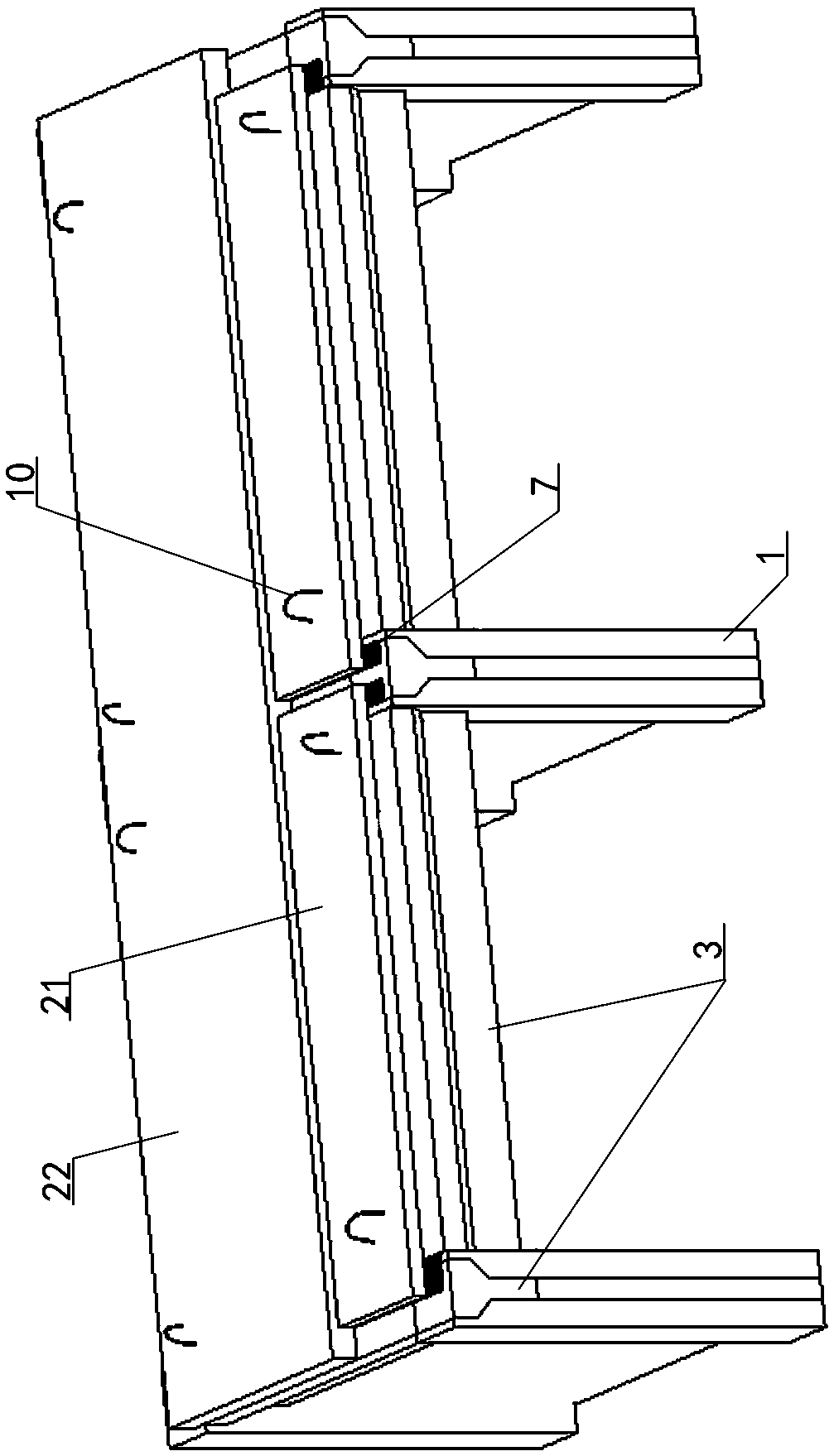
[0035] Embodiment one sees Figure 1-2 As shown, a concrete silo roof structure includes a silo wall 1 and a roof 2. The roof covers the silo and is fixedly connected to the top of the silo wall.

[0036] The roof includes a prefabricated lower part 21 and a cast-in-place upper part 22, the prefabricated lower part is a prefabricated reinforced concrete slab, the size of the prefabricated lower part 21 is smaller than the size of the silo, and the prefabricated lower part 21 is lapped on the silo wall 1 to cover the silo The inner space of the cast-in-place upper part 22 is a cast-in-place concrete layer laid with steel mesh sheets 23, the outer contour size of the cast-in-place upper part is equal to the outer contour size of the silo, and the cast-in-place upper part is cast-in-place on the upper side of the prefabricated lower part, Together with the prefabricated lower part it forms the roof.

[0037] The concrete silo roof structure also includes roof supporting corbels ...

Embodiment 2

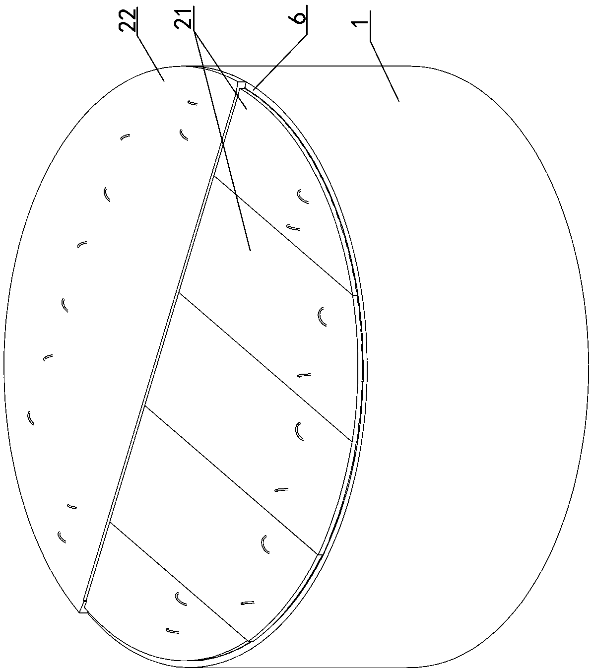
[0042]Embodiment two see Figure 3-4 As shown, the difference from Embodiment 1 is that the silo is a circular silo, the silo wall is a ring, the roof supporting corbels also form a ring along the silo wall, and the prefabricated lower part is a set of strips Shaped prefabricated slabs, arranged in the same direction, the width of the strip prefabricated slabs is the same, the edge of the strip prefabricated slab is lapped on the roof support corbel, and the edge shape of the strip prefabricated slab is set along the roof support corbel to match the roof support The arc that matches the arc of the corbel.

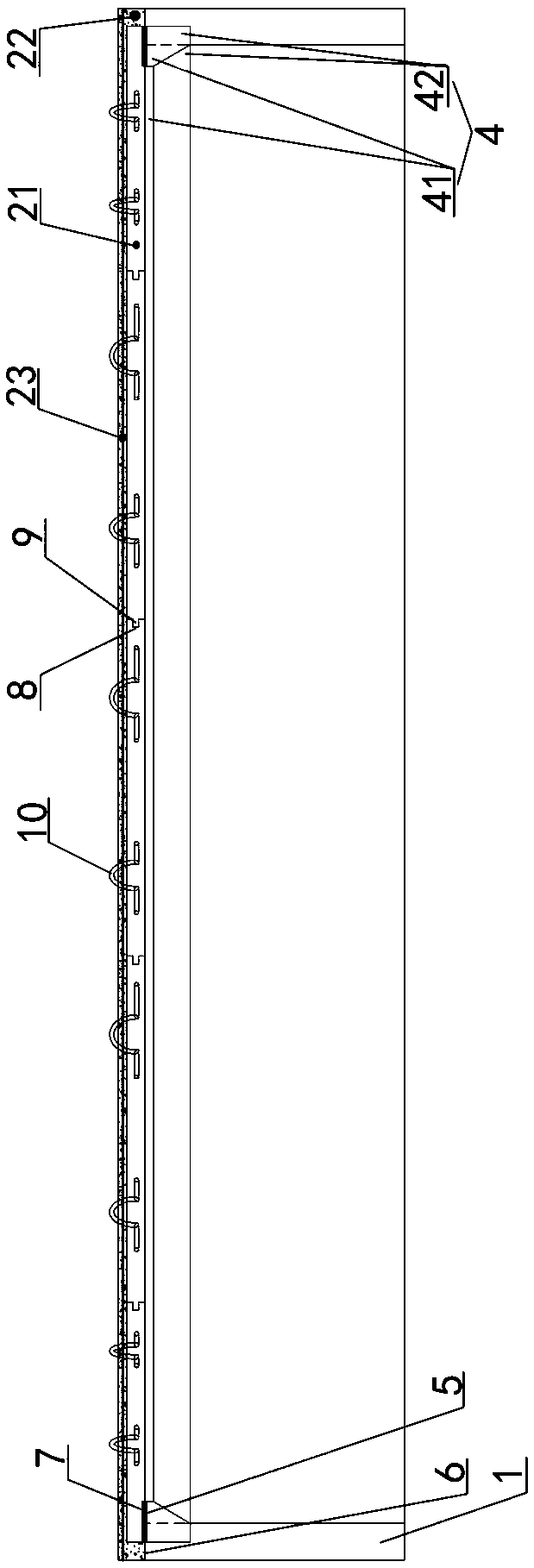
[0043] The roof supporting bracket is located on the top inner side of the warehouse wall 1, and the top supporting bracket is a second bracket 4. The cross section of the second bracket 4 is wide at the top and narrow at the bottom, and the second bracket 4 includes from bottom to top. The second upper part 41 and the second lower part 42, the second upper part 41 has a r...


PUM


Abstract

The invention discloses a concrete silo top plate structure and a construction method thereof. The concrete silo top plate structure comprises a silo wall and a top plate. The top plate comprises a prefabricated lower part, a cast-in-situ upper part and a top plate supporting bracket. The prefabricated lower part is a fabricated plate, and the cast-in-situ upper part is a cast-in-situ layer pavedwith a reinforcing mesh. The cast-in-situ upper part and the prefabricated lower part form the top plate jointly, and the top plate supporting bracket and the surface of the upper side of the silo wall are flush. The silo wall and the surface of the upper side of the top plate supporting bracket form a lap-joint plane jointly, and the lap-joint plane comprises lap-joint areas and connecting areas.The two ends of the prefabricated lower part are connected to the lap-joint areas on the two sides in a lapped mode, and the parts, making contact with the bracket, in the lap-joint areas are fixed through bonding layers. The upper side of the prefabricated lower part is covered with concrete of the cast-in-situ upper part, and the upper sides of the connecting areas are filled with the concreteof the cast-in-situ upper part. According to the solving scheme, the construction process of the silo top plate is simplified, the construction procedure is accelerated, the construction cost is reduced, a superimposing mode of the prefabricated plate and in-situ casting is adopted, the characteristic that the construction speed of a prefabricated structure is high is sufficiently utilized, and the construction integrality requirement of the silo top plate is met.

Description

technical field [0001] The invention relates to a concrete roof structure, in particular to a vertical silo roof concrete structure and a construction method thereof. Background technique [0002] At present, in the reinforced concrete cylinder structure, the roof of the vertical silo is usually cast-in-place. The common method is to use the high-support formwork to build a scaffold, or use the vertical silo sliding form system, and use the steel frame and steel pipe truss as the support. The way the frame supports the formwork. The above construction methods all require a large amount of manpower and materials to be invested in the formwork support frame; at the same time, the traditional construction method often has a large height of the working surface, and there is a large safety risk. The construction investment is large and the construction period is long, resulting in construction period and cost. The substantial increase of the formwork system has a long period of ...

Claims


Application Information

Patent Timeline
Patent Type & Authority Applications(China)
IPC IPC(8): E04H7/00
CPCE04H7/00Y02A40/51
Inventor 赵西方苏阳汪晓龙卢传东梅晓丽杨晓毅谭海燕
Owner THE THIRD CONSTR OF CHINA CONSTR FIRST GROUP
Why Eureka
Try Eureka