
Intermediate infrared high-reflection optical element test apparatus and test method based on optical parameter oscillator

A technology of optical components and optical parameters, which is used in optical instrument testing, machine/structural component testing, measuring devices, etc., can solve the problems of complex structure of deuterium fluoride chemical lasers, inconvenient testing of optical components, and high operating costs, and achieves the use of The effect of low cost, high reliability, high power density

Active Publication Date: 2018-07-10
NAT UNIV OF DEFENSE TECH
View PDF10 Cites 3 Cited by
  • Summary
  • Abstract
  • Description
  • Claims
  • Application Information

AI Technical Summary

Problems solved by technology

Although the deuterium fluoride chemical laser can achieve high power output of mid-infrared continuous laser, its operating cost is very high, and it can only test the optical components for tens of seconds, and it cannot be tested for a long time (10 4 s level) test; in addition, the deuterium fluoride chemical laser has a complex structure and a huge volume, and there are many inconveniences in the test of optical components

Method used


Image

  • Intermediate infrared high-reflection optical element test apparatus and test method based on optical parameter oscillator
  • Intermediate infrared high-reflection optical element test apparatus and test method based on optical parameter oscillator
  • Intermediate infrared high-reflection optical element test apparatus and test method based on optical parameter oscillator

Examples


Embodiment Construction

[0036] In order to make the object, technical solution and advantages of the present invention clearer, the implementation manner of the present invention will be further described in detail below in conjunction with the accompanying drawings.

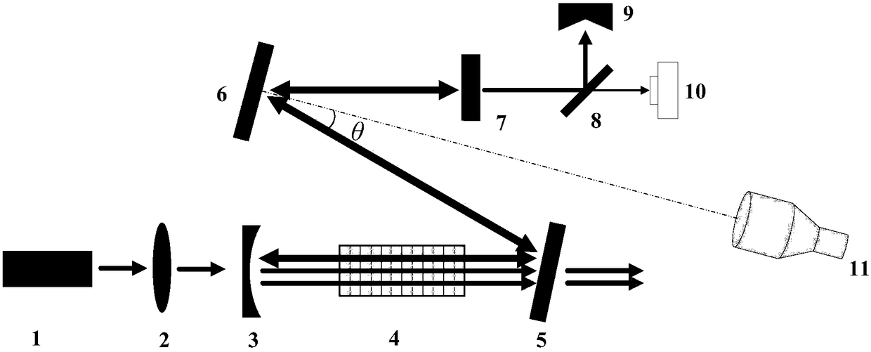
[0037] see figure 1 , the mid-infrared high-reflection optical element testing device based on an optical parametric oscillator provided by the present invention includes a near-infrared fiber laser 1, a pump coupling optical system 2, a high-reflection cavity mirror 3, a nonlinear frequency conversion crystal 4, and a dichroic mirror 5 , a mid-infrared high-reflection optical element 6 to be tested, a coupling output mirror 7, a mid-infrared spectroscope 8, a power meter 9, a mid-infrared camera 10, and a monitoring system 11; wherein the high-reflection cavity mirror 3, the dichroic mirror 5, the to-be-tested The mid-infrared highly reflective optical element 6 and the outcoupling mirror 7 form a resonant cavity of a closed-cavity op...


PUM


Abstract

The invention relates to an intermediate infrared high-reflection optical element test apparatus and test method based on an optical parameter oscillator. The intermediate infrared high-reflection optical element test apparatus comprises a near-infrared optical-fiber laser, a pumping coupling optical system, a high-reflection endoscope, a nonlinear variable-frequency crystal, a dichroic mirror, ato-be-detected intermediate infrared high-reflection optical element, a coupling output mirror, an intermediate infrared beam splitter, a power meter, an intermediate infrared camera and a monitoringsystem; and the high-reflection endoscope, the dichronic mirror, the to-be-detected intermediate infrared high-reflection optical element and the coupling output mirror form a resonant cavity of a closed-cavity optical parameter oscillator. By adopting the optical parameter oscillator of the closed-cavity structure, the radiation conditions of the high power density, long time and intermediate infrared continuous laser in the resonant cavity can be realized, and the laser damage-resisting capability of the intermediate infrared high-reflection optical element can be tested. The intermediate infrared high-reflection optical element test apparatus and test method have the characteristics of full solid structure, full-power operation, small size, convenience in operation, high reliability, and low application cost, and capability in long-time low-cost stable operation.

Description

technical field [0001] The present invention relates to the field of optical component testing, and more specifically, relates to a device that uses closed-cavity optical parametric oscillator technology to realize high power density and long-term laser irradiation testing and assessment of optical components in the mid-infrared band. The device can It is widely used in the testing and assessment of highly reflective optical components in the mid-infrared band. Background technique [0002] The damage resistance of optical components is directly related to the reliability and service life of the laser system. Scientific and accurate testing, assessment, and evaluation of the damage resistance and service life of optical components are the basis for ensuring the stable and reliable operation of the laser system. With the continuous improvement of the output power of continuous wave high-energy laser systems, higher and higher requirements are put forward for the anti-laser d...

Claims


Application Information

Patent Timeline
Patent Type & Authority Applications(China)
IPC IPC(8): G01M11/02
CPCG01M11/00Y02E10/50
Inventor 韩凯奚小明李霄娄兆凯程曦李志鸿宋锐习锋杰闫宝珠杨轶许晓军
Owner NAT UNIV OF DEFENSE TECH
Learn More