Optical cable knocking signal displaying method and system

A technology of percussion signal and display method, applied in radio wave measurement system, voice analysis, utilization of re-radiation, etc., can solve the problems of long refresh time, limited intensity discrimination, poor image authenticity, etc., to shorten the refresh time and improve the Real-time performance, the effect of reducing the amount of data

Active Publication Date: 2018-07-10
INNO INSTR (CHINA) INC
View PDF10 Cites 9 Cited by
  • Summary
  • Abstract
  • Description
  • Claims
  • Application Information

AI Technical Summary

Problems solved by technology

[0003] In the market, there are currently some products that only display the strength of the detected knocking signal on the display screen, and the intensity discrimination is also limited, which cannot truly and intuitively reflect the situation of the actually collected knocking signal
There are also some products that display the size of the knocking signal in the form of an image, and then refresh the next waveform when the screen is full. The tapping signal and the image signal seen by the eyes may be out of sync. After hearing the tapping sound, it will take a while to see the tapping signal on the screen, and it is impossible to accurately judge whether it is the current tapping signal from the image; In addition, the realism of the displayed image is poor, and it is not easy to distinguish the noise from the knocking signal. Only by looking at the image, sometimes it is impossible to know whether it is the knocking signal or the noise

Method used


Image

  • Optical cable knocking signal displaying method and system
  • Optical cable knocking signal displaying method and system
  • Optical cable knocking signal displaying method and system

Examples


Embodiment Construction

[0036] In order to make the above objects, features and advantages of the present invention more comprehensible, specific implementations of the present invention will be described in detail below in conjunction with the accompanying drawings.

[0037] In the following description, numerous specific details are set forth in order to provide a thorough understanding of the present invention. However, the present invention can be implemented in many other ways different from those described here, and those skilled in the art can make similar extensions without violating the connotation of the present invention, so the present invention is not limited by the specific implementations disclosed below.

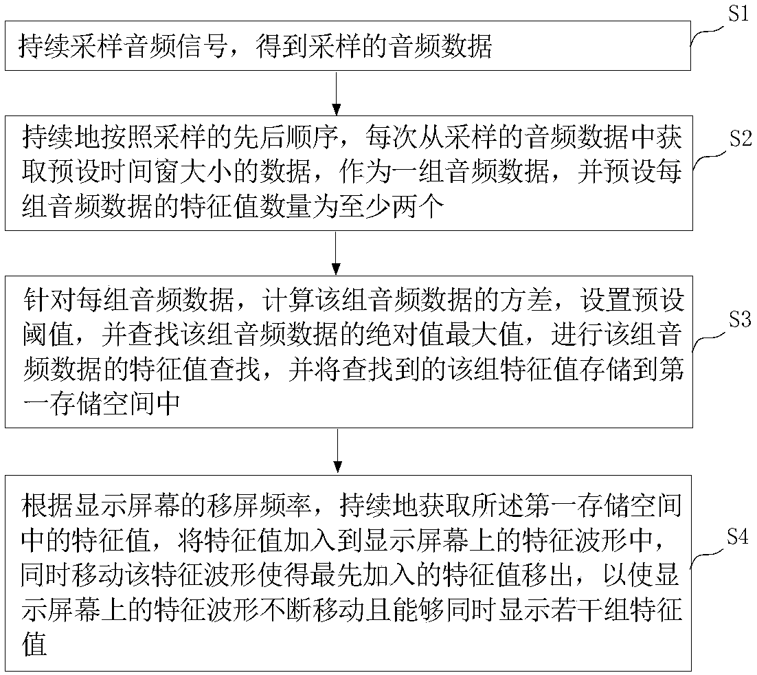
[0038] see figure 1 , in one embodiment, the optical cable tapping signal display method comprises the following steps:

[0039] S1: Continuously sample the audio signal to obtain the sampled audio data;

[0040] S2: Continuously according to the order of sampling, obtain the data...


PUM


Abstract

The invention provides an optical cable knocking signal displaying method and system. The optical cable knocking signal displaying method includes the steps: continuously sampling audio signals to obtain the audio data of sampling; continuously according to the sequence of sampling, every time obtaining the data of the magnitude of the preset time window from the audio data of sampling, taking thedata of the magnitude of the preset time window as one group of audio data, and presetting the characteristic value number of each group of audio data as at least two; for the each group of audio data, setting a preset threshold, looking for the maximum of the absolute value of the group of the audio data, looking for the characteristic value of the group of audio data, and storing the group of characteristic value in the first storage space; and according to the screen movement frequency of a display screen, continuously obtaining the characteristic values in the first storage space, addingthe characteristic values in the characteristic waveform, and at the same time, moving the characteristic waveform to remove the earliest added characteristic value so as to enable the characteristicwaveform on the display screen to move continuously and display a plurality of groups of characteristic values at the same time. The optical cable knocking signal displaying method can improve timeliness and authenticity of display of identified knocking signals.

Description

technical field [0001] The invention relates to the technical field of image display processing of measuring instruments, in particular to a method and system for displaying optical cable knocking signals. Background technique [0002] There are many measurement items in the optical fiber measurement technology, including the percussion measurement test of the optical fiber, which can reflect the distance of the percussion fiber by identifying the percussion sound, and locate the position of the percussion fiber, or can identify the percussion Tap sound to identify tapped fibers among multiple fibers, etc. [0003] In the market, there are currently some products that only display the strength of the detected knocking signal on the display screen, and the degree of intensity differentiation is limited, which cannot truly and intuitively reflect the situation of the actually collected knocking signal. There are also some products that display the size of the knocking signal ...

Claims


Application Information

Patent Timeline
IPC IPC(8): G10L21/12G10L21/0208G10L21/0316G10L25/48G01S11/14
CPCG01S11/14G10L21/0208G10L21/0316G10L21/12G10L25/48
Inventor 李楚元
Owner INNO INSTR (CHINA) INC
Why Eureka
Try Eureka