Cooling plate

A cooling plate and partition technology, applied in the field of mechanical processing, can solve problems such as poor integrity, poor circulation effect, and difficult product quality assurance, and achieve the effects of easy installation and transportation, optimized manufacturing process, and shortened manufacturing cycle

Pending Publication Date: 2018-07-13
MAANSHAN MAILI MACHINERY MFR
View PDF0 Cites 0 Cited by
  • Summary
  • Abstract
  • Description
  • Claims
  • Application Information

AI Technical Summary

Problems solved by technology

[0002] At present, in the existing cooling plate, it belongs to the splicing assembly, so there are more welds, and the original cooling plate has more welds. The six cooling surfaces are superimposed by rectangular seamless steel pipes (80*30*3) and then welded on the front and back. There are many welds, and there are as many as 164 welds in the whole product. It is easy to weld the rectangular seamless steel pipe through during welding, and it is easy to produce waste products. The product quality is not easy to guarantee, and the circulating water is easy to leak, and the circulation effect is not good. , the original product is a splicing product, the front and back sides are superimposed by 11 rectangular seamless steel pipes, and the overall splicing is poor. After splicing each surface, it is difficult to ensure the flatness of the product. The total weight of the set is 342.5k

Method used


Image

  • Cooling plate
  • Cooling plate

Examples


Embodiment Construction

[0021] The following will clearly and completely describe the technical solutions in the embodiments of the present invention with reference to the accompanying drawings in the embodiments of the present invention. Obviously, the described embodiments are only some, not all, embodiments of the present invention. All other embodiments obtained by persons of ordinary skill in the art based on the embodiments of the present invention belong to the protection scope of the present invention.

[0022] According to an embodiment of the present invention, a cooling plate is provided.

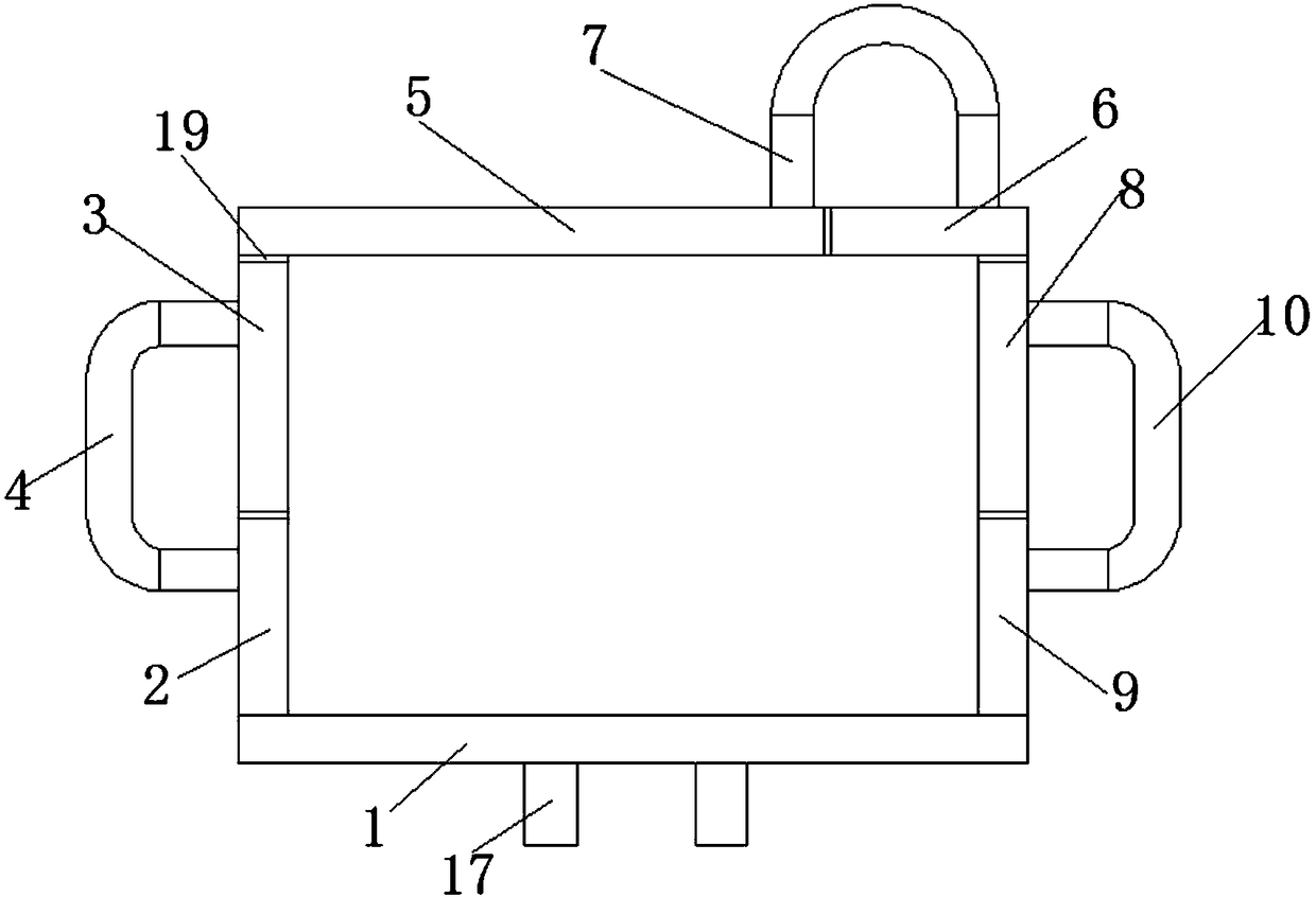
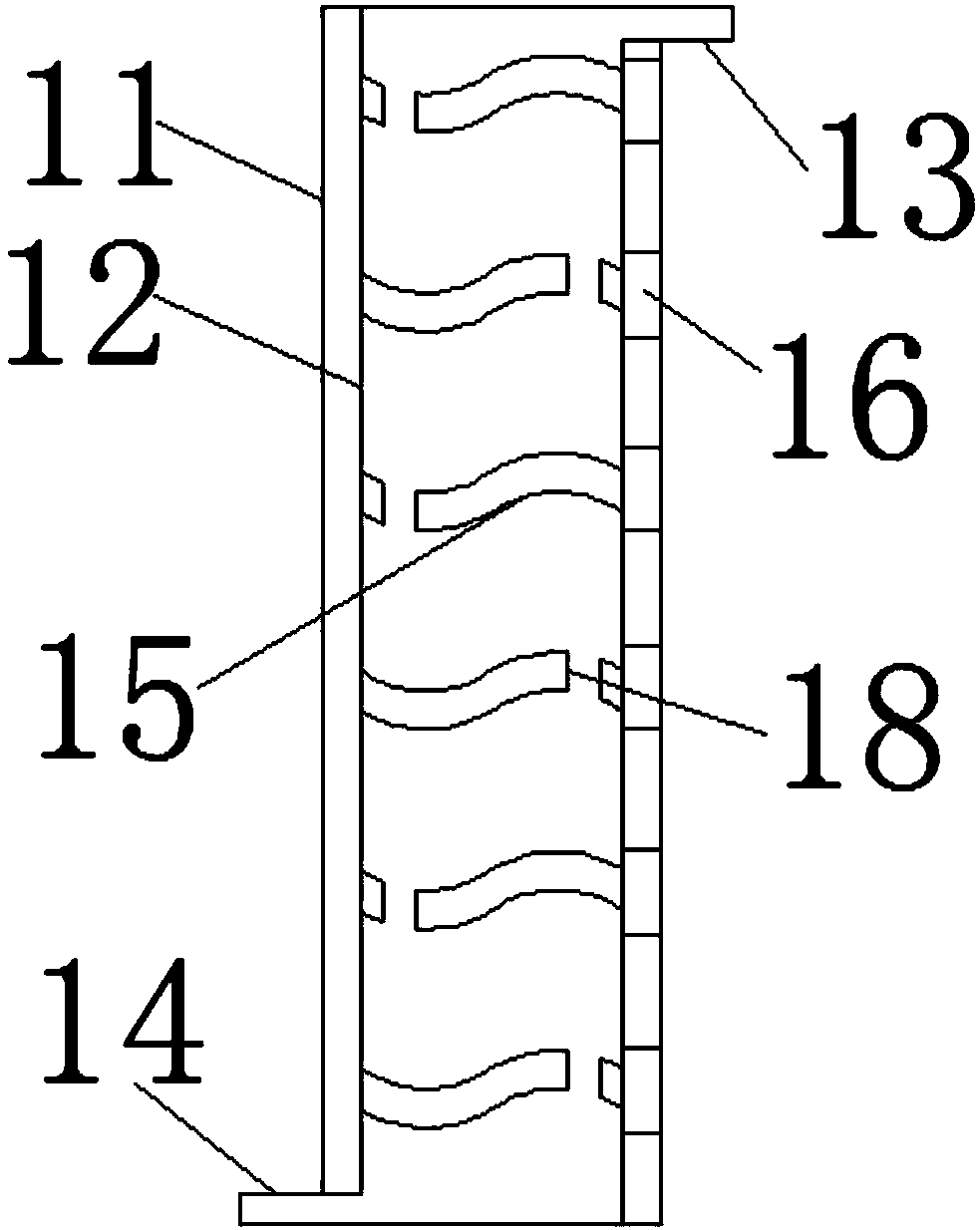
[0023] like Figure 1-2 As shown, a cooling plate according to an embodiment of the present invention includes a layered cabinet plate 1, and a cooling plate-2 is provided on the upper end side of the layered inner partition plate 1, and the cooling plate-2 is far away from the partition One end of the partition plate 1 in the layer is provided with a cooling plate two 3, and one side of the cooling pl...


PUM


Abstract

The invention discloses a cooling plate. The cooling plate comprises a layered inner pavilion plate, and a cooling plate I is arranged on one side of the upper end of the layered inner partition plate; a cooling plate II is arranged at one end, far away from the layered inner partition plate, of the cooling plate I, and a circulating water channel partition plate I is arranged on one side of the cooling plate I; the other end of the circulating water channel partition plate I is connected with the cooling plate II, and the end, far away from the cooling plate I, of the cooling plate I is provided with a cooling plate III; the cooling plate III and layered inner partition plate are arranged in parallel, and a cooling plate IV is arranged at one end, far away from the cooling plate II, of the cooling plate III; a circulating water channel partition plate II is arranged at the upper end of the cooling plate III, and the other end of the circulating water channel partition plate II is connected with the cooling plate IV; and a cooling plate V is arranged at the lower end of one side, far away from the cooling plate III, of the cooling plate IV. The cooling plate has the beneficial effects that the flatness and the stability of products are solved, the improved and upgraded six cooling plates are made of stainless steel plates, so that weld joints are reduced, and the manufacturingprocess is simplified.

Description

technical field [0001] The invention relates to the field of mechanical processing, in particular to a cooling plate. Background technique [0002] At present, in the existing cooling plate, it belongs to the splicing assembly, so there are more welds, and the original cooling plate has more welds. The six cooling surfaces are superimposed by rectangular seamless steel pipes (80*30*3) and then welded on the front and back. There are many welds, and there are as many as 164 welds in the whole product. It is easy to weld the rectangular seamless steel pipe through during welding, and it is easy to produce waste products. The product quality is not easy to guarantee, and the circulating water is easy to leak, and the circulation effect is not good. , the original product is a splicing product, the front and back sides are superimposed by 11 rectangular seamless steel pipes, and the overall splicing is poor. After splicing each surface, it is difficult to ensure the flatness of ...

Claims


Application Information

Patent Timeline
Patent Type & Authority Applications(China)
IPC IPC(8): B22D11/055
CPCB22D11/055
Inventor 李安
Owner MAANSHAN MAILI MACHINERY MFR
Why Eureka
Try Eureka