Automatic engraving machine and engraving method

A grinding and automatic technology, which is applied to machine tools, grinding machines, grinding/polishing equipment, etc., which are suitable for grinding workpiece planes, can solve the problems of poor positioning and machining accuracy, complex structure, etc., and achieve improved machining accuracy and simple operation , The effect of improving positioning accuracy

Inactive Publication Date: 2018-07-13
YUNNAN NORMAL UNIV
View PDF6 Cites 3 Cited by
  • Summary
  • Abstract
  • Description
  • Claims
  • Application Information

AI Technical Summary

Problems solved by technology

[0003] The purpose of the invention is to solve the problems of complex structure, poor positioning and processing accuracy of the existing grinding machine, and the invention provides an automatic grinding machine and a grinding method

Method used


Image

  • Automatic engraving machine and engraving method
  • Automatic engraving machine and engraving method
  • Automatic engraving machine and engraving method

Examples


specific Embodiment approach 1

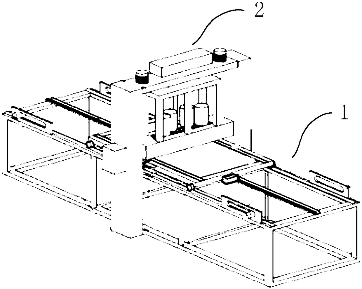
[0040] Specific implementation mode one: see figure 1 with figure 2 Describe this embodiment, an automatic grinding machine described in this embodiment, including a controller, a horizontal moving part 1 and a processing part 2;

[0041] The controller is used to control the horizontal moving part 1 to move forward and backward in the horizontal direction, and is also used to control the processing part 2 to move up and down in the vertical direction, so that the processing part 2 can process the workpiece to be processed on the horizontal moving part 1. processing;

[0042] Both the processing part 2 and the horizontal moving part 1 are provided with limit switches 5, and the limit switches 5 are used to sense the limit positions of the processing part 2 and the horizontal moving part 1, and upload them to the controller.

[0043] In this embodiment, the automatic grinding machine is simple in structure, and the introduction of the limit switch 5 accurately limits the mov...

specific Embodiment approach 2

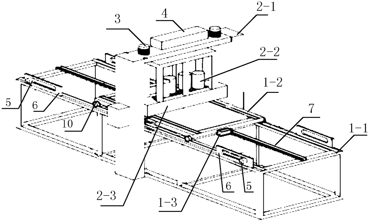
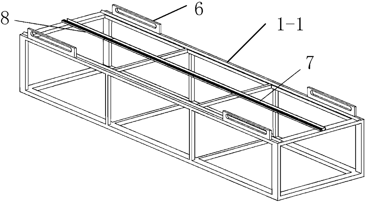
[0044] Specific implementation mode two: see Figure 1 to Figure 4 Describe this embodiment. The difference between this embodiment and the automatic grinding machine described in Embodiment 1 is that the horizontal moving part 1 includes a base 1-1, a workbench 1-2, and a stepping motor 1-3;

[0045] The workbench 1-2 is slidingly connected with the two slide rails on the base 1-1 through the roller 10;

[0046] The stepper motor 1-3 is used to drive the workbench 1-2 to move forward and backward along the two slide rails on the base 1-1.

[0047] In this embodiment, the horizontal moving part 1 has a simple structure and is easy to operate.

specific Embodiment approach 3

[0048] Specific implementation mode three: see Figure 1 to Figure 5 Describe this embodiment, the difference between this embodiment and the automatic grinding machine described in the second embodiment is that the processing part 2 includes a faucet frame 2-1, N AC motors 2-2 and a gear box 2-3;

[0049] The faucet frame 2-1 is a door-shaped structure, and straddles the top of the horizontal moving part 1;

[0050] The gear box 2-3 is fixed on the beam of the faucet frame 2-1 through the spring column 3;

[0051] The faucet frame 2-1 is also provided with an air pump 4, which is used to control the gear box 2-3 to move up and down between the beam of the faucet frame 2-1 and the workbench 1-2;

[0052] N AC motors 2-2 are fixed on the gear box 2-3, and the N AC motors 2-2 drive the grinding head 9 to rotate through the gear box 2-3, and the grinding head 9 is used to process the workpiece on the horizontal moving part 1 parts for processing;

[0053] N is an integer great...


PUM


Abstract

The invention discloses an automatic engraving machine and an engraving method, relates to an automatic engraving machine and belongs to the field of intelligent control. The problems that existing engraving machines are complex in structure and poor in positioning and machining precision are solved. The automatic engraving machine comprises a controller, a horizontal moving part and a machining part; the controller is used for controlling the horizontal moving part to move forwards and backwards in the horizontal direction and further used for controlling the machining part to move up and down in the vertical direction, so that the machining part machines a to-be-machined workpiece on the horizontal moving part; and the machining part and the horizontal moving part are both provided withlimit switches, and the limit switches are used for inducting limit positions of the machining part and the horizontal moving part and uploading the limit positions to the controller. The automatic engraving machine is mainly used for engraving metal plates.

Description

technical field [0001] The invention relates to an automatic grinding machine. It belongs to the field of intelligent control. Background technique [0002] In the prior art, the processing of some metal plates needs to be ground on its surface, but the used grinding machine has the defects of complex structure, poor positioning and processing accuracy. Therefore, it is urgent to provide a solution to the above technical problems. Grinder. Contents of the invention [0003] The purpose of the invention is to solve the problems of complex structure, poor positioning and processing precision of the existing grinding machine, and the invention provides an automatic grinding machine and a grinding method. [0004] An automatic grinding machine, including a controller, a horizontal moving part 1 and a processing part 2; [0005] The controller is used to control the horizontal moving part 1 to move forward and backward in the horizontal direction, and is also used to control...

Claims


Application Information

Patent Timeline
Patent Type & Authority Applications(China)
IPC IPC(8): B24B7/02B24B1/00
Inventor 罗毅杨昆董兴华
Owner YUNNAN NORMAL UNIV
Why Eureka
Try Eureka