
Unmanned aerial vehicle charging pile

A technology of unmanned aerial vehicles and charging piles, applied in the field of unmanned aerial vehicles, can solve the problems of affecting work efficiency, limited power, increase costs, etc., and achieve the effect of improving work efficiency

Pending Publication Date: 2018-07-13
SHANGHAI TOPXGUN ROBOT CO LTD
View PDF6 Cites 30 Cited by
  • Summary
  • Abstract
  • Description
  • Claims
  • Application Information

AI Technical Summary

Problems solved by technology

[0003]In various industry applications, drones usually need to carry various equipment to achieve various functions. With the increase of equipment, the weight of drones increases, It needs to consume more power to ensure the normal flight of the UAV, and the power consumption is relatively large
However, drones are basically powered by batteries. The battery can provide limited power at one time, and the battery life is low. It is necessary to prepare multiple batteries at the same time and control the drone to land every once in a while to replace the battery, so as to enhance its battery life. The process is cumbersome, and the drone needs to disassemble and assemble the battery many times during the mission, which not only affects the work efficiency, but also easily damages the drone's electronic components and rack due to high-frequency disassembly and assembly, which increases the cost
Due to the limitation of battery technology level, battery life is the biggest technical challenge faced by current multi-rotor UAVs

Method used


Image

  • Unmanned aerial vehicle charging pile
  • Unmanned aerial vehicle charging pile
  • Unmanned aerial vehicle charging pile

Examples


Embodiment

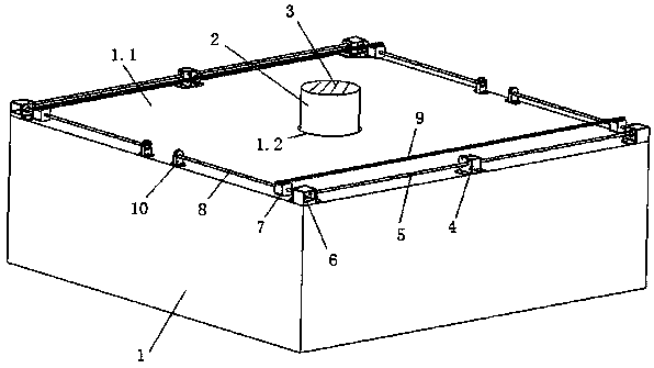
[0032] At present, drones basically rely on batteries for power supply. The battery can provide limited power at one time, and the battery life is low. It is necessary to prepare multiple batteries at the same time and control the drone to land every once in a while to replace the battery, enhance its battery life, and operate The process is cumbersome, and the UAV needs to disassemble and assemble the battery many times during the mission, which not only affects the work efficiency, but also easily damages the electronic components and rack of the UAV, which increases the cost. Although wireless charging piles are used to charge UAVs nowadays, the current UAV charging piles have a complex structure, and it is difficult to automatically locate the charging position of the UAV, and the wireless charging device is exposed outside, which is easily affected by the external environment. The impact of the battery is damaged, which affects the service life of the wireless charging dev...


PUM


Abstract

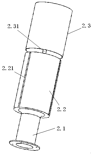
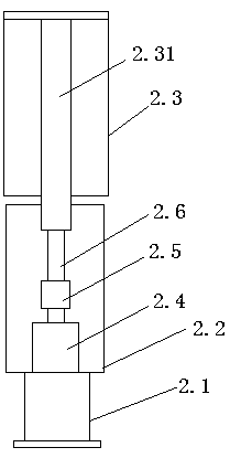
The invention relates to the technical field of unmanned aerial vehicles, in particular to an unmanned aerial vehicle charging pile which comprises a base, a liftable charging platform, a wireless charging device and a group of sliding rod positioning mechanisms. The base comprises a top landing platform and a containing space inside, the liftable charging platform is arranged in the containing space and ascends and descends relative to the landing platform to charge the unmanned aerial vehicles berthed on the landing platform, the wireless charging device is fixed at the top of the liftable charging platform, and the sliding rod positioning mechanisms are arranged on the landing platform oppositely and used for pushing the unmanned aerial vehicles berthed on the landing platform to the liftable charging platform for positioning to complete charging. When an unmanned aerial vehicle is insufficient in power quantity, the unmanned aerial vehicle charging pile can provide an unmanned aerial vehicle landing and charging platform and automatically position the unmanned aerial vehicle to enable the same to be effectively docked with the wireless charging device on the liftable charging platform to complete automatic charging, and manual replacement of batteries is not needed, so that working efficiency of the unmanned aerial vehicle is improved.

Description

technical field [0001] The invention relates to the technical field of drones, in particular to a charging pile for drones. Background technique [0002] A drone is an unmanned aerial vehicle operated by a radio remote control device or its own program control device. With the rapid development of the drone industry, more and more drones are being applied to industries such as agriculture, forestry, electric power, surveying and mapping, and telemetry. [0003] In various industry applications, drones usually need to be equipped with various equipment to achieve various functions. With the increase of equipment, the weight of the drone increases, and it needs to consume more power to ensure the normal flight of the drone. Power loss is large. However, drones are basically powered by batteries. The battery can provide limited power at one time, and the battery life is low. It is necessary to prepare multiple batteries at the same time and control the drone to land every onc...

Claims


Application Information

Patent Timeline
Patent Type & Authority Applications(China)
IPC IPC(8): B64F1/00B60L11/18
CPCB64F1/00B60L53/12B60L2200/10Y02T10/70Y02T10/7072Y02T90/14
Inventor 张逸群朱昶霖尹亮亮张羽
Owner SHANGHAI TOPXGUN ROBOT CO LTD
Learn More