Variable-stiffness double-arm automatic tensioner

A technology of variable stiffness and tensioner, applied in the field of transmission system, can solve the problems that the belt tension cannot ensure the design value, the tensioner is difficult to ensure the working position, and the installation of the single-arm tensioner is difficult, so as to avoid noise, large noise, etc. Installation space, the effect of prolonging the service life

Pending Publication Date: 2018-07-13
SOUTH CHINA UNIV OF TECH
View PDF9 Cites 6 Cited by
  • Summary
  • Abstract
  • Description
  • Claims
  • Application Information

AI Technical Summary

Problems solved by technology

However, due to the existence of manufacturing errors such as the position of the belt and the wheel train, it is difficult to install the single-arm tensioner during installation, and af

Method used


Image

  • Variable-stiffness double-arm automatic tensioner
  • Variable-stiffness double-arm automatic tensioner
  • Variable-stiffness double-arm automatic tensioner

Examples


Embodiment 1

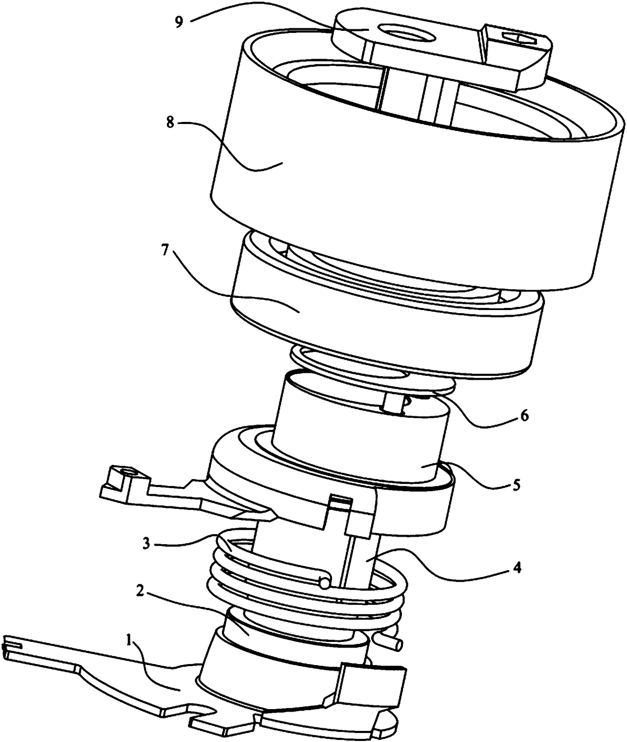
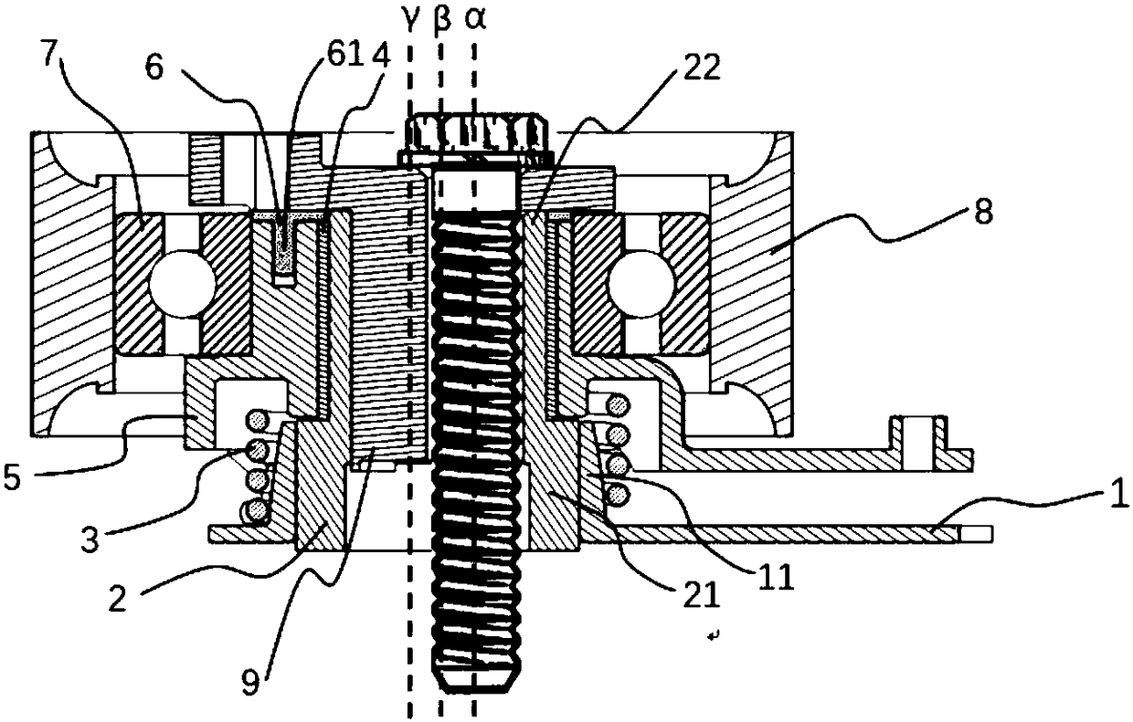
[0035] Such as Figure 1 to Figure 4A double-arm automatic tensioner with variable stiffness is shown, including an adjusting arm 9, a working arm 5, a pivot shaft 2, a bushing 4, a bottom plate 1, a torsion spring 3, a rolling bearing 7 and a pulley 8, and the adjusting arm 9 is passed through A bolt is mounted on the engine body, the pivot shaft 2 is pivotally mounted on the adjusting arm 9, the working arm 5 is pivotally mounted on one end of the pivot shaft 2 through a bushing 4, and the pivot shaft The other end of 2 is connected with the base 1, and the base 1 is fixed on the engine body through a bolt, and the torsion spring 3 is torsionally set between the bottom plate 1 and the working arm 5, while the torsion spring 3. The torsion arms at both ends are respectively fixedly connected with the bottom plate 1 and the working arm 5; the pulley 8 is mounted on the working arm 5 through a rolling bearing 7, and the pivot center and the geometric center of the adjusting arm...

Embodiment 2

[0046] Such as Figure 9 As shown, the difference between this embodiment and Embodiment 1 is that: the cylindrical boss 11 is an equidiametric cylindrical shape with a cross-sectional diameter consistent up and down, and the torsion spring 3 is a coil spring with variable middle diameter and equal pitch. It shows that the middle diameter of the torsion spring 3 starts to decrease gradually along the direction away from the base 1, and is conical, correspondingly, as Figure 10 As shown, the spring stiffness Ke in the second embodiment is compared with the torsional spring stiffness K of the prior art 0 , when the torsion spring 3 is loaded to a certain angle, that is, the working arm 5 is twisted to a certain angle θ 0 , the spring stiffness Kt becomes larger, and the stiffness changes will vary with the speed of the change of the spring pitch diameter.

Embodiment 3

[0048] Such as Figure 11 As shown, the difference between the third embodiment and the second embodiment is that the shown torsion spring 3 adopts a coil spring with variable middle diameter and variable pitch, and the middle diameter of the shown torsion spring 3 gradually becomes smaller along the direction away from the base 1, and the pitch The distance also changes synchronously. Correspondingly, as Figure 12 As shown, the spring stiffness K in this embodiment f Compared with the prior art torsion spring stiffness K 0 , when the torsion spring 3 is loaded to a certain angle, that is, the working arm 5 is twisted to a certain angle θ 0 , spring stiffness K f becomes larger; and the second embodiment is Figure 9 Compared with the structure in the middle, the spring structure with variable pitch diameter will have a different stiffness change from that of the spring with only variable pitch diameter.

[0049] The above-mentioned embodiments can realize that when the...


PUM


Abstract

The invention discloses a variable-stiffness double-arm automatic tensioner. The variable-stiffness double-arm automatic tensioner comprises an adjusting arm, a working arm, a pivotal shaft, a bush, abottom plate, a torsion spring, a rolling bearing and a belt wheel; the adjusting arm is arranged on an engine body through a bolt; the pivotal shaft is arranged on the adjusting arm; the working armis arranged on one end of the pivotal shaft in a pivotal mode through the bush; the other end of the pivotal shaft is connected with a base; the base is fixed on the engine body through a plug pin; the torsion spring is arranged between the bottom plate and the working arm in a torsion and sleeving manner and is separately fixedly connected with the bottom plate and the working arm; the belt wheel is arranged on the working arm through the rolling bearing; and part of the inner ring of the torsion spring is gradually contacted with the outer peripheral wall of the bottom plate in a torsion angle changing process to change the torsion stiffness of the torsion spring. By adopting the variable-stiffness double-arm automatic tensioner, error compensation capability during assembly of the tensioner can be increased, and spring stiffness can be changed; a tension arm is prevented from being impacted with a limiting device to generate noise; and the service life of the tensioner is prolonged.

Description

technical field [0001] The invention relates to the field of transmission systems, in particular to a double-arm automatic tensioner with variable stiffness, which is designed for the timing belt transmission system of automobiles. Background technique [0002] Since the timing belt was put into use in the 1960s and 1970s, its market share has been increasing. Timing belt transmission combines many advantages of toothed transmission and belt transmission, and is a transmission method with high precision and compact structure. The torque value of the tensioner is controlled by the spring element, relying on the inherent properties of the spring element, when loading, it can accumulate a certain amount of elastic potential energy, and when it is unloaded, it can quickly release the elastic potential energy, so that the change of belt length can be produced. Better responsiveness. [0003] In the patent US6149542A, a double-arm automatic tensioner is proposed. The tensioner is...

Claims


Application Information

Patent Timeline
IPC IPC(8): F16H7/10
CPCF16H7/10F16H2007/088F16H2007/081
Inventor 龙尚斌上官文斌徐谱
Owner SOUTH CHINA UNIV OF TECH
Why Eureka
Try Eureka