Automatic transmission mechanical parking mechanism

A technology of automatic transmission and parking mechanism, which is applied in the direction of mechanical equipment, transmission device control, and components with teeth, etc., which can solve the problem of difficult position guarantee, difficult control of parking brake spring leaf bending angle, and spring leaf spring Problems such as fast force value attenuation, etc., achieve the effect of improving reliability

Pending Publication Date: 2018-07-13
CHONGQING TSINGSHAN IND
View PDF8 Cites 5 Cited by
  • Summary
  • Abstract
  • Description
  • Claims
  • Application Information

AI Technical Summary

Problems solved by technology

see Image 6 , at present, a kind of automatic transmission parking mechanism used on the market, the shift arm assembly is composed of the shift arm seat and the shift arm welded together and is fixedly connected with the shift shaft through the roll pin, the parking The vehicle brake spring plate assembly a6 is fixed on the transmission case through fixing bolts and guide bolts, and its component roller a6-1 is pressed on the shift arm a3; the component push rod a9-1 of the roller push rod assembly Cooperate with the hole of the shifting arm, and the parking guide plate is fixed on the transmission case by bolts. The defects of this parking mechanism are: 1. The position of the roller a6-1 of the parking brake spring plate assembly a6 The bending angle of the parking brake spring is difficult to guarantee and the bending angle of the parking brake spring is difficult to control. The processing of the parts is difficult and the quality is difficult to control; and the spring force of the spring decays quickly. After repeated movements, the spring force has a greater decrease than the initial value. Small, which seriously affects the shift feel of the vehicle

Method used


Image

  • Automatic transmission mechanical parking mechanism
  • Automatic transmission mechanical parking mechanism
  • Automatic transmission mechanical parking mechanism

Examples


Embodiment Construction

[0032] Referring to the accompanying drawings, specific embodiments of the present invention will be described in detail.

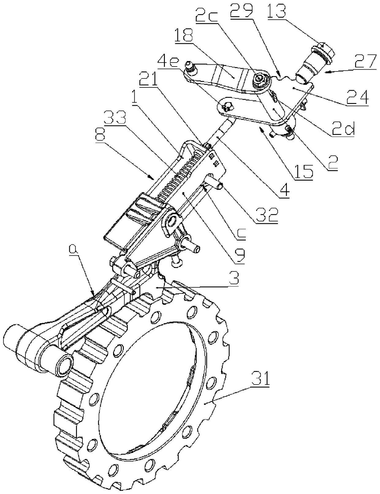
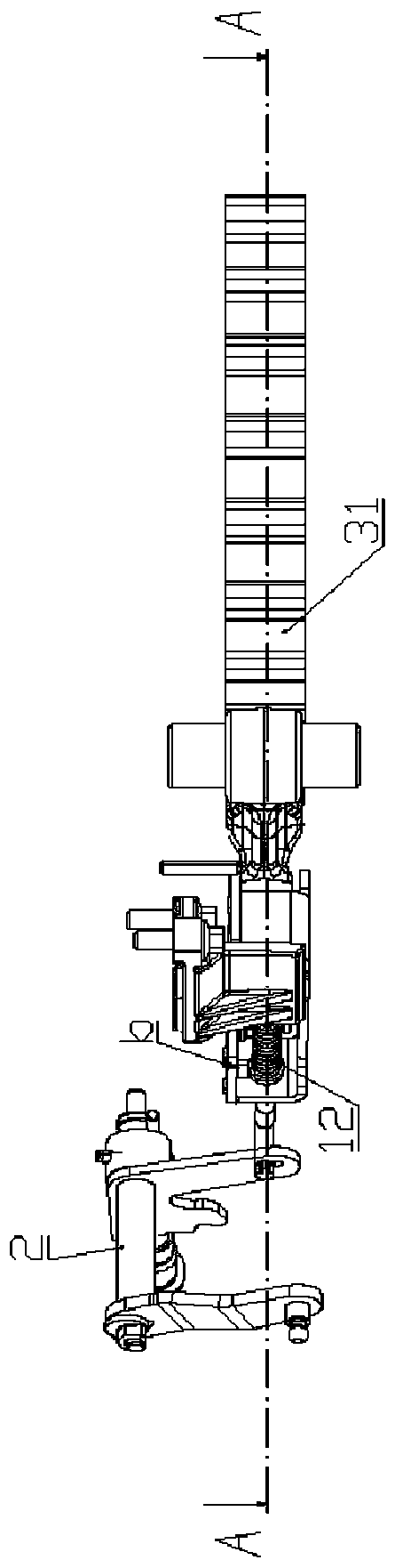
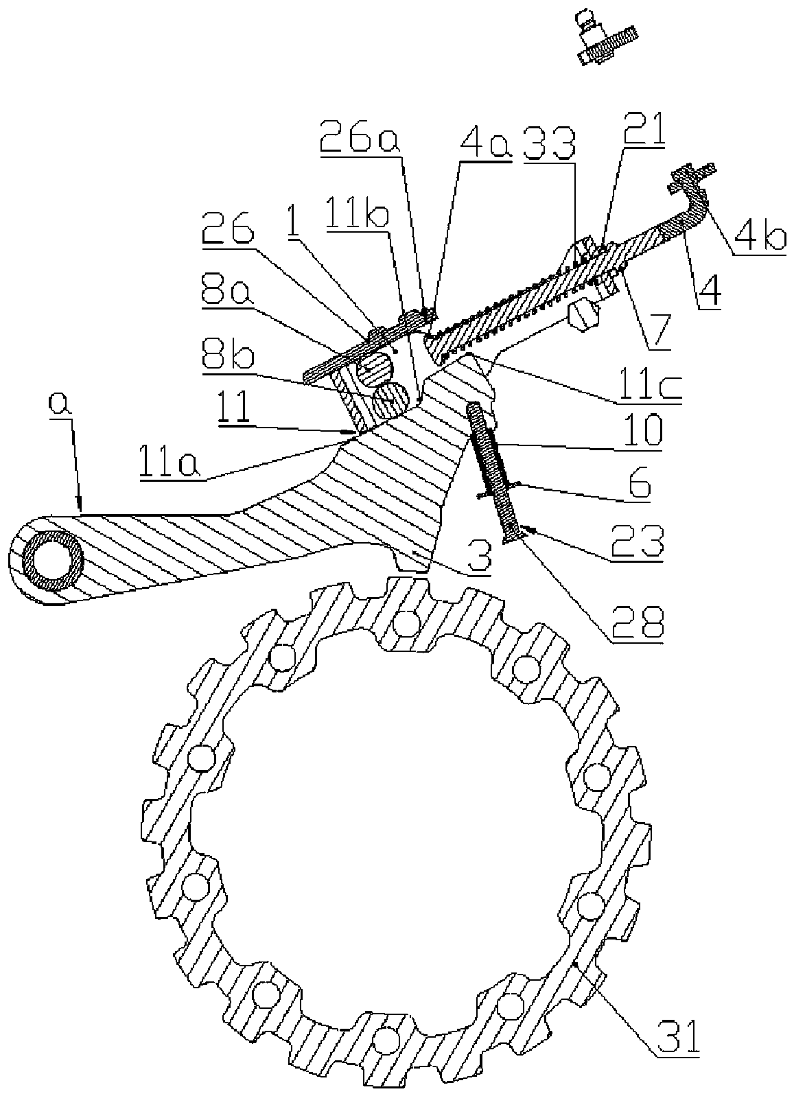
[0033] see Figure 1 to Figure 5 , an embodiment of the mechanical parking mechanism of the automatic transmission, the mechanical parking mechanism of the automatic transmission includes a parking ratchet 31 circumferentially fixed on the transmission shaft system, and a parking pawl hinged on the transmission case 30 a, the mechanical parking mechanism of an automatic transmission, including a parking ratchet 31 circumferentially fixed on the transmission shaft, and a parking pawl a hinged on the transmission case 30 . Preferably, the parking ratchet 31 is circumferentially fixed on the differential rotating housing 34 in the transmission shaft system, and the parking ratchet 31 is installed on the differential housing, which solves the problem that the parking ratchet 31 is installed on the input shaft. , Under severe working conditions, the input sha...


PUM


Abstract

The invention relates to an automatic transmission mechanical parking mechanism. The automatic transmission mechanical parking mechanism comprises a parking ratchet wheel circumferentially fixed to atransmission shaft system. A gear shifting rotary shaft is arranged on a transmission box. One end of the gear shifting rotary shaft is fixedly connected with a gear shifting rotary arm, and the otherend of the gear shifting rotary shaft is fixedly connected with a parking rotary arm. The parking rotary arm is in an L shape. The short arm end of the L-shaped parking rotary arm is provided with sectored teeth. An elastic compression lock pin is arranged on the transmission box. The long arm end of the L-shaped parking rotary arm is hinged to a parking push-pull rod. The extension end of the parking push-pull rod is inserted into a parking driving frame which is in sliding fit with the transmission box. The extension end, inserted into the parking driving frame, of the parking push-pull rodis sleeved with a push rod compression spring. One end of the push rod compression spring is limited by a convex edge of the extension end of the parking push-pull rod, and the other end of the pushrod compression spring is limited by an end plate of the parking driving frame. A first roller makes rolling contact with the lower end face of a guide plate, and a second roller makes rolling contactwith the free end of a parking detent. The transmission box is provided with a reset device corresponding to the free end of the parking detent.

Description

technical field [0001] The invention relates to an automobile transmission, in particular to a mechanical parking mechanism of an automatic transmission. Background technique [0002] In order to ensure that there will be no dangerous situations such as slipping and slopes after the vehicle is parked, a parking mechanism must be installed in the automatic transmission. The rotation direction is turned to realize the static of the vehicle, so as to ensure the safety of the owner's life and property. Therefore, the parking mechanism is an indispensable safety device for automatic transmission vehicles. see Figure 6 , at present, a kind of automatic transmission parking mechanism used on the market, the shift arm assembly is composed of the shift arm seat and the shift arm welded together and is fixedly connected with the shift shaft through the roll pin, the parking The vehicle brake spring plate assembly a6 is fixed on the transmission case through fixing bolts and guide b...

Claims


Application Information

Patent Timeline
Patent Type & Authority Applications(China)
IPC IPC(8): F16H63/34F16H63/38
CPCF16H63/3408F16H63/3425F16H63/38
Inventor 王超胡敏陈成马连严洪侯亚斌尹生黄捷苏航
Owner CHONGQING TSINGSHAN IND
Why Eureka
Try Eureka