Optical design method of light guide plate

A technology of optical design and light guide plate, which is applied in optics, optical components, light guides, etc., can solve the problems of high design and development costs, complex design and development methods of light guide plate, and long design and development cycle, so as to shorten the optical development cycle and optimize the optical Excellent effect of design and development process and performance indicators

Inactive Publication Date: 2018-07-13
苏州欧匹希光电有限公司
View PDF3 Cites 7 Cited by
  • Summary
  • Abstract
  • Description
  • Claims
  • Application Information

AI Technical Summary

Problems solved by technology

[0004] In the prior art, the design and development method of the light guide plate is complicated, resulting in a long design and development cycle and high design and development costs

Method used


Image

  • Optical design method of light guide plate
  • Optical design method of light guide plate
  • Optical design method of light guide plate

Examples


Embodiment Construction

[0028] The following will clearly and completely describe the technical solutions in the embodiments of the present invention with reference to the accompanying drawings in the embodiments of the present invention. Obviously, the described embodiments are only some, not all, embodiments of the present invention. Based on the embodiments of the present invention, all other embodiments obtained by persons of ordinary skill in the art without creative efforts fall within the protection scope of the present invention.

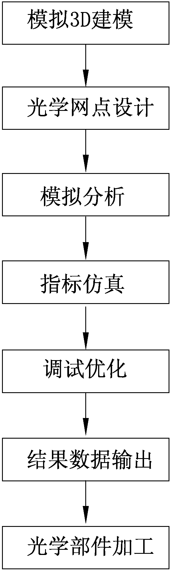
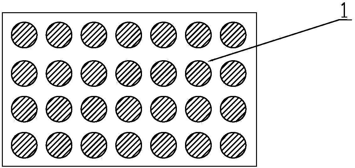
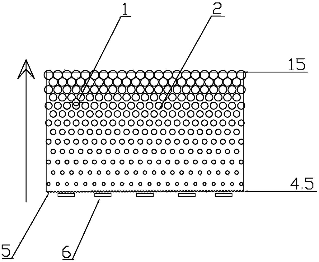
[0029] according to figure 1 , figure 2 , image 3 with Figure 4 , The present invention provides an optical design method of a light guide plate, including three-dimensional modeling, dot design, simulation analysis, simulation index, debugging optimization, result output, and light guide plate processing.

[0030] The optical design method of the light guide plate is to design the density of the diffused dots on the light guide plate 5 and the size of the di...


PUM


Abstract

The invention discloses an optical design method of a light guide plate. The method comprises the steps of three-dimensional modeling, dot designing, simulating and analyzing, index simulating, debugging and optimizing, result outputting, and light guide plate machining. According to the optical design method of the light guide plate, the density, the size and the microscopic-carving scale (V-cut)of diffusion dots on the light guide plate are designed. Meanwhile, the method is matched with the mold designing and machining technology, so that the uniformity and the high brightness of the emergent light intensity of the light guide plate are achieved. According to the invention, the design sequence of the optical design method of the light guide plate sequentially comprises the steps of three-dimensional modeling, dot designing, simulating and analyzing, index simulating, debugging and optimizing, result outputting, and light guide plate machining. According to the appearance, size andsimulation indexes of the light guide plate, the analog simulation design of the light guide plate is realized. Based on the analog simulation method, the optical design and the development process ofthe light guide plate are optimized, and the optical development period of the light guide plate is shortened. The design and development cost of the light guide plate is reduced. The light guide plate is excellent in various performance indexes, short in machining period and high in efficiency.

Description

technical field [0001] The invention relates to the technical equipment field of a light guide plate, in particular to an optical design method of a light guide plate. Background technique [0002] Liquid crystal display, referred to as LCD (Liquid Crystal Display), is at the high end of the electronic information industry chain and is a key component of digital complete machine products such as digital TV, computer, and mobile communication terminal. The LCD itself does not emit light, and the backlight module is a necessary component to provide light. The most important technical core of the backlight module is the light guide plate, which is an optical-grade acrylic / PC board, which has a very high reflectivity and is a high-tech material that does not absorb light. The dots on the bottom surface of the high-grade acrylic / PC board use the optical-grade acrylic board to absorb the light emitted from the LED lamp and stay on the surface of the optical-grade acrylic / PC board...

Claims


Application Information

Patent Timeline
Patent Type & Authority Applications(China)
IPC IPC(8): G02B6/00G02B27/00
Inventor 李超吴栋梁
Owner 苏州欧匹希光电有限公司
Why Eureka
Try Eureka