Scissor-like frame linkage over-constraint double-layer annular truss deployable antenna mechanism

A ring truss and linkage technology, applied in the direction of rotating antennas, folding antennas, etc., can solve the problems of reducing the reliability of the overall structure, complex tensioning zippers, and easy winding, etc., to achieve simple structure, large folding ratio, and reduce manufacturing costs and the effect of difficulty

Pending Publication Date: 2018-07-13
YANSHAN UNIV
View PDF0 Cites 4 Cited by
  • Summary
  • Abstract
  • Description
  • Claims
  • Application Information

AI Technical Summary

Problems solved by technology

With the increasing demand for large-aperture antennas in various space missions, the caliber of the deployable antenna becomes larger and larger, and the single-layer ring truss-type deployable antenna mechanism cannot meet the rigidity of the truss mechanism when the caliber increases to a certain extent. As well as the requirements of surface accuracy, and some ring truss deployable antennas use tension zippers to improve the overall stiffness of the antenna mechanism, but the tension zippers are more complicated and difficult to control, which also reduces the reliability of the overall structure. Winding is prone to occur. Therefore, it is urgent to develop an excellent expandable mechanism with large diameter, high precision, high stiffness, high stability, and large folding ratio on the basis of the existing ring truss configuration to meet the requirements of different spaceflight applications. task requirements

Method used


Image

  • Scissor-like frame linkage over-constraint double-layer annular truss deployable antenna mechanism
  • Scissor-like frame linkage over-constraint double-layer annular truss deployable antenna mechanism
  • Scissor-like frame linkage over-constraint double-layer annular truss deployable antenna mechanism

Examples


Embodiment Construction

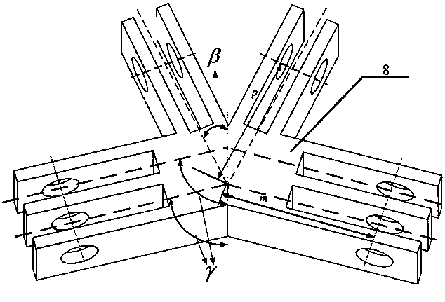
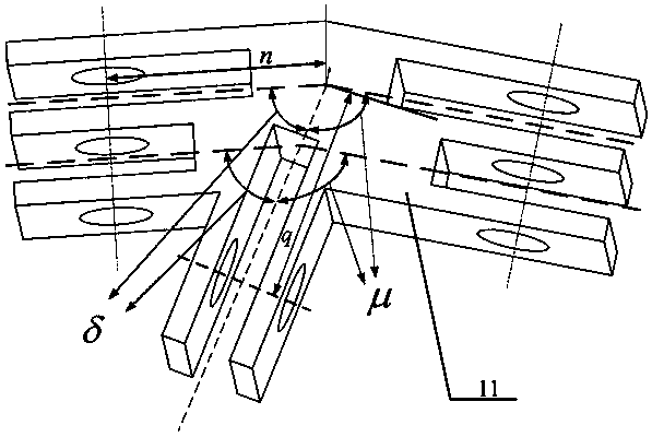
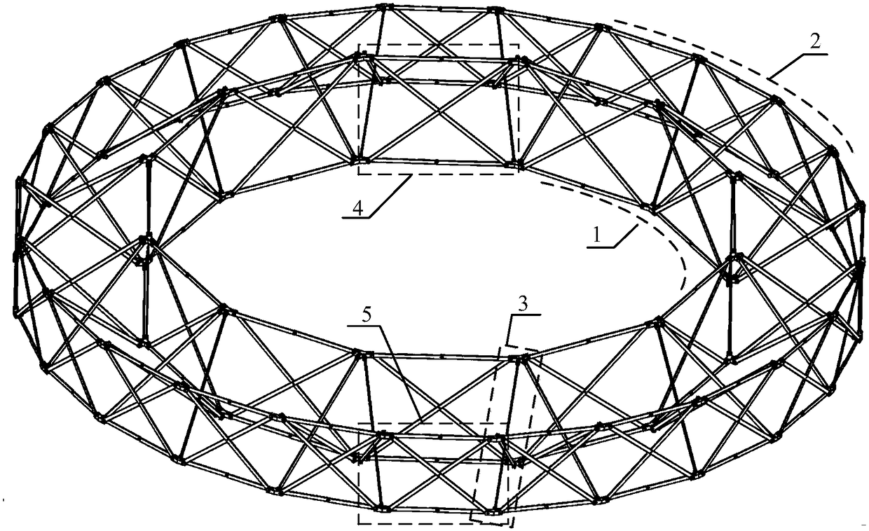
[0041] exist figure 1 , figure 2 , image 3 and Figure 4 In the schematic diagram of the deployable antenna mechanism of the shear-hinge linkage type over-constrained double-layer ring truss, the inner layer ring truss assembly 1 includes 12 inner layer folding units 4, and the structure of each inner layer folding unit is exactly the same, and the adjacent inner layer The folding units are connected through the shared upper and lower inner layer faceplates 8 to form an inner ring truss assembly, which is a multi-faceted ring truss structure after being unfolded and folded; the outer ring truss assembly 2 includes 24 outer layers Folding unit 5, the structure of each outer layer folding unit is exactly the same, and the adjacent outer layer folding units are connected by the shared upper and lower outer layer faceplates 11 to form the outer layer ring truss assembly. After the outer layer ring truss assembly is unfolded and folded Both are multi-faceted ring truss structu...


PUM


Abstract

The invention discloses a scissor-like frame linkage over-constraint double-layer annular truss deployable antenna mechanism which mainly comprises an inner annular truss component, an outer annular truss component and an inner and outer truss connecting component. The inner annular truss component comprises n inner folding and unfolding units, two adjacent inner folding and unfolding units are connected through an upper inner flower disc and a lower inner flower disc which are shared, the outer annular truss component comprises 2n outer folding and unfolding units, two adjacent outer foldingand unfolding units are connected through an upper outer flower disc and a lower outer flower disc which are shared, the inner and outer truss connecting component comprises 2n middle folding and unfolding units, the inner annular truss component and the outer annular truss component are concentrically arranged, and the upper inner flower disc and the lower inner flower disc of each side of each inner folding and unfolding unit are connected with the upper outer flower disc and the lower outer flower disc of each side of the corresponding outer folding and unfolding unit through the middle folding and unfolding units. The antenna mechanism has the advantages of high stiffness and reliability and simple structure and is applied to communication satellites, space stations and space detectors.

Description

technical field [0001] The invention relates to a deployable mechanism, in particular to a deployable antenna mechanism. Background technique [0002] At present, major aerospace science and technology projects such as planetary exploration, space station construction, spacecraft design, manned spaceflight, and lunar exploration programs are inseparable from space deployable mechanisms. Large-scale space deployable mechanisms are an important application in the aerospace field. It is used as the deployment and support mechanism of the spaceborne antenna. Spaceborne antennas are widely used in ground-to-ground wireless communications, electronic reconnaissance, navigation, remote sensing, and scientific research. They are the "eyes" and "ears" of satellite systems and play a decisive role. Due to the long distance, the signal received by the satellite is weak. In order to meet the requirements of multi-function, multi-band, large capacity and high power, the space-borne ante...

Claims


Application Information

Patent Timeline
Patent Type & Authority Applications(China)
IPC IPC(8): H01Q1/08
CPCH01Q1/084
Inventor 赵永生韩博张硕许允斗姚建涛陈阳郑东
Owner YANSHAN UNIV
Why Eureka
Try Eureka