Eureka AIR delivers breakthrough ideas for toughest innovation challenges, trusted by R&D personnel around the world.

UHF RFID card reader system and card reader antenna thereof

A card reader and antenna technology, applied in the directions of antennas, antenna parts, antenna grounding devices, etc., can solve the problems of excessive size and complex antenna structure, achieve simple antenna structure, simple feeding structure, and realize the overall system structure. simplistic effect

Active Publication Date: 2018-07-13
GUANGDONG MIKWAVE COMM TECH
View PDF7 Cites 11 Cited by
  • Summary
  • Abstract
  • Description
  • Claims
  • Application Information

AI Technical Summary

Problems solved by technology

[0003] Based on this, it is necessary to provide a UHF RFID card reader system and its card reader antenna with a simple antenna structure in view of the complex structure and excessive size of the traditional global UHF RFID card reader antenna

Method used


Image

  • UHF RFID card reader system and card reader antenna thereof
  • UHF RFID card reader system and card reader antenna thereof
  • UHF RFID card reader system and card reader antenna thereof

Examples


Embodiment Construction

[0029] In order to facilitate the understanding of the present invention, the present invention will be described more fully below with reference to the associated drawings. Preferred embodiments of the invention are shown in the accompanying drawings. However, the present invention can be embodied in many different forms and is not limited to the embodiments described herein. On the contrary, these embodiments are provided to make the understanding of the disclosure of the present invention more thorough and comprehensive.

[0030] It should be noted that when an element is referred to as being “fixed” to another element, it can be directly on the other element or there can also be an intervening element. When an element is referred to as being "connected to" another element, it can be directly connected to the other element or intervening elements may also be present. The terms "vertical," "horizontal," "left," "right," and similar expressions are used herein for purposes ...


PUM

PropertyMeasurementUnit
Lengthaaaaaaaaaa
Widthaaaaaaaaaa
Thicknessaaaaaaaaaa

Abstract

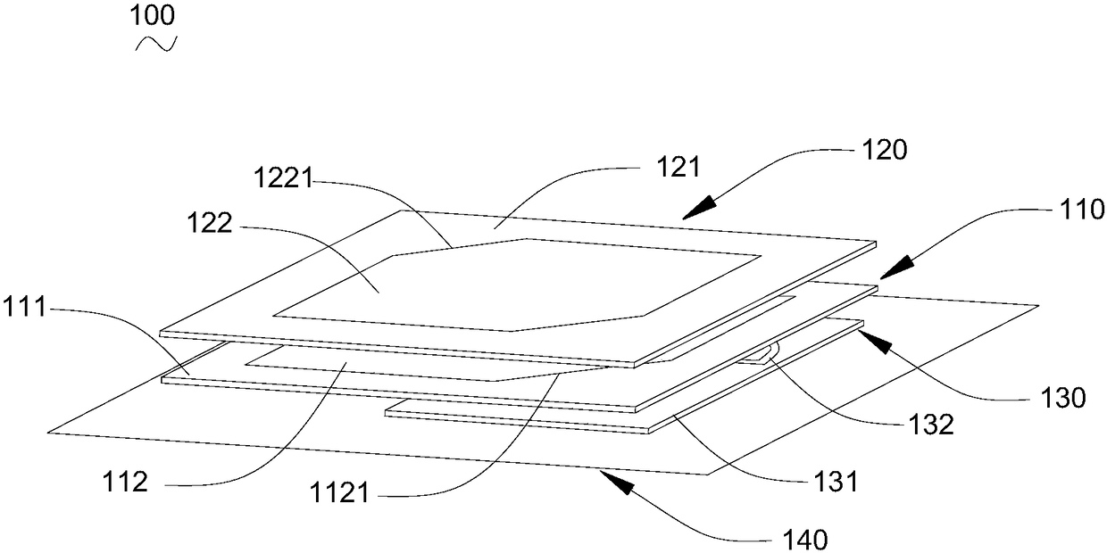
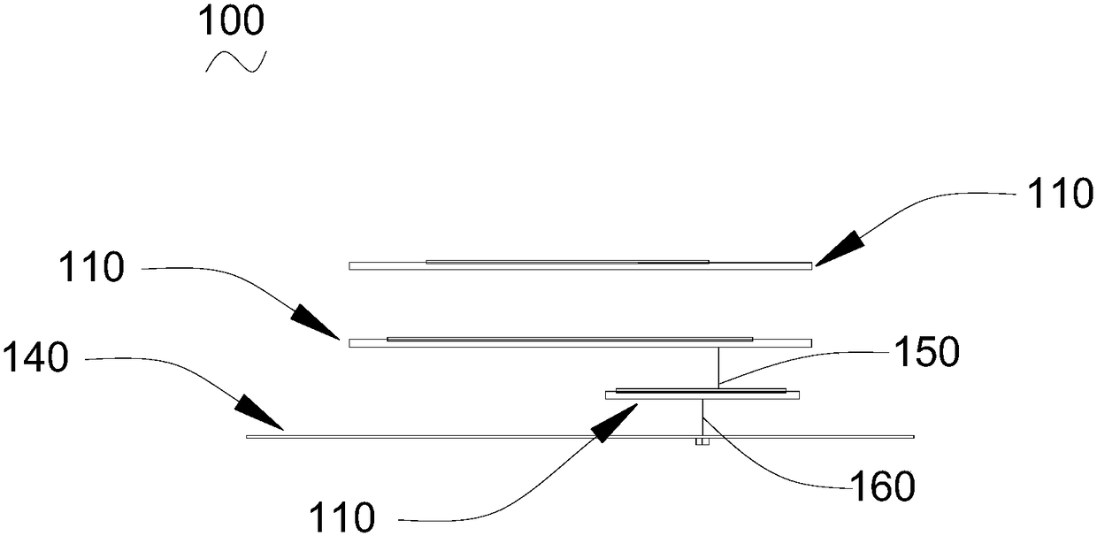
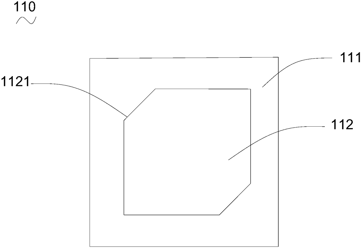
The invention relates to a UHF RFID card reader antenna. The antenna comprises radiation unit layers with radiation patches, parasitic patch layers with parasitic patches, feed structural layers withfeed strips and metal floors; the parasitic patch layers are oppositely arranged on one sides, towards the radiation patches, of the radiation unit layers at intervals; the feed structural layers areoppositely arranged on one sides, back to the parasitic patch layers, of the radiation unit layers at intervals; the metal floors are oppositely arranged on one sides, back to the radiation unit layers, of the feed structural layers at intervals; in addition, the two ends of the feed strips are electrically connected with the metal floors and the radiation patches; and the feed strips adopt a shape of an Archimedean helical curve, and a width gradually-changed structure. The UHF RFID card reader antenna is simple in feed structure, so that the overall antenna structure is simple in structure.The invention also relates to a UHF RFID card reader system which comprises the UHF RFID card reader antenna. Therefore, the UHF RFID card reader system can be applicable to the use frequency band ofthe world-wide UHF RFID, and simplification and miniaturization of the overall system structure can be realized.

Description

technical field [0001] The invention relates to the technical field of electronic information, in particular to a UHF RFID card reader system and a card reader antenna thereof. Background technique [0002] UHF RFID card reader, that is, ultra-high frequency radio frequency identification card reader, is a non-contact automatic identification device that can read electronic tag data. It is widely used in various fields due to its long reading and writing distance and high reading and writing speed. In, for example: highway toll system and train monitoring system, etc. At present, different countries and regions around the world have different standards for the division of UHF. Different frequency division standards lead to different design requirements of antenna products, which increases the manufacturing cost of antenna products. In order to solve the above problems, an ultra-wideband antenna and a universal UHF radio frequency identification card reader that can cover t...

Claims


Application Information

Patent Timeline
IPC IPC(8): H01Q1/38H01Q1/48H01Q1/50H01Q1/22G06K7/10
CPCG06K7/10297H01Q1/2208H01Q1/38H01Q1/48H01Q1/50
Inventor 苏道一朱永忠
Owner GUANGDONG MIKWAVE COMM TECH
Why Eureka
Eureka Blog
Learn More