Efficient solar conversion photovoltaic power generation system

A photovoltaic power generation system and photovoltaic power generation panel technology, applied in the photovoltaic field, can solve problems such as inconvenience in operation, and achieve the effects of convenient operation, good protection, and convenient handling and operation.

Inactive Publication Date: 2018-07-13
成都亿伏科技有限公司
View PDF4 Cites 2 Cited by
  • Summary
  • Abstract
  • Description
  • Claims
  • Application Information

AI Technical Summary

Problems solved by technology

[0004] The technical problem to be solved by the present invention is: the front installation operation is to separate the bracket and the photovoltaic power generation panel, which needs to be assembled on site. High-efficiency solar energy conversion photovoltaic power generation system

Method used


Image

  • Efficient solar conversion photovoltaic power generation system
  • Efficient solar conversion photovoltaic power generation system
  • Efficient solar conversion photovoltaic power generation system

Examples


Embodiment 1

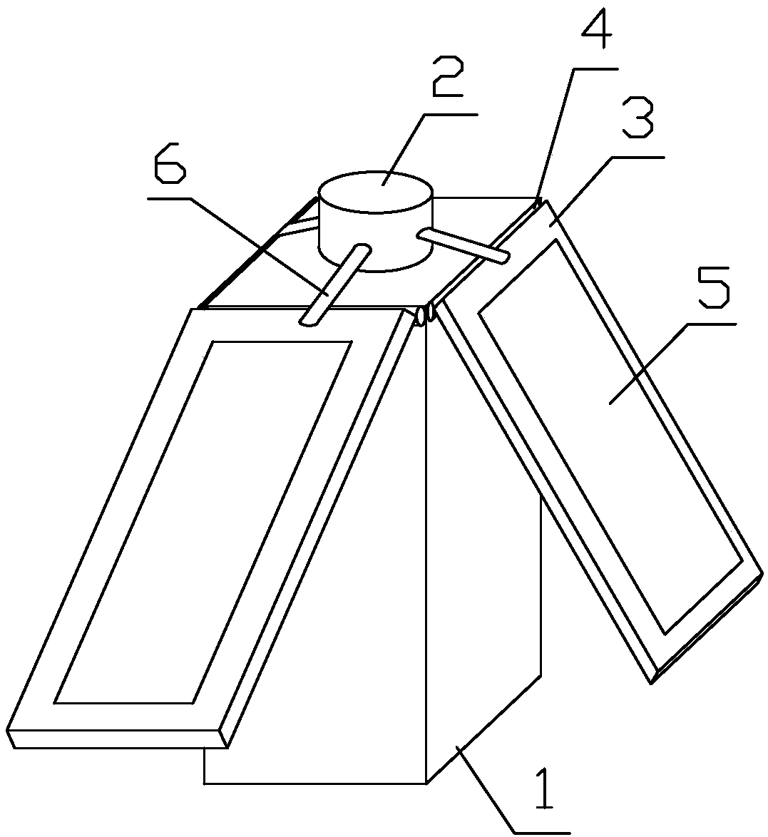
[0033]The high-efficiency solar energy conversion photovoltaic power generation system includes a fixed column 1, the radial cross section of which is a regular polygon; Mounting plate 3, the lower surface of one end of the long axis direction of the mounting plate 3 is connected with the side wall near the top of the fixed column 1 through the rotation shaft 4, the axial direction of the rotating shaft 4 is parallel to the side of the fixed column 1 where it is located, and the upper plate of the mounting plate 3 There is a groove 12 on the surface, and the photovoltaic power generation panel 5 is embedded in the groove 12; it also includes a number of telescopic rods 6, one axial end of the telescopic rod 6 is fixed in the installation shell 2, and the other end is connected to the long axis direction end of the installation plate 3 The upper surface of the upper plate is connected by the universal joint 7; through the contraction or elongation of the telescopic rod 6, the in...

Embodiment 2

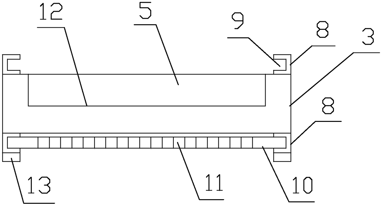
[0035] Further improvement on the basis of Embodiment 1, positioning strips 8 are protruded on both sides of the lower plate surface of the mounting plate 3 along the long axis direction, and the long axis direction of the positioning strips 8 is parallel to the long axis direction of the mounting plate 3 The opposite side walls of the two positioning bars 8 are provided with a card slot 9, the extension direction of the card slot 9 is parallel to the axial direction of the positioning bar 8, and the extension length of the card slot 9 is greater than the length of the major axis of the photovoltaic power generation panel 5, less than the length of the major axis of the mounting plate 3. The positioning strip 8 on the lower surface of the mounting plate 3 is provided with a rubber buffer layer 13, and when the mounting plate 3 rotates downward to the side of the fixed column 1 where the mounting plate 3 is parallel, the rubber buffer layer 13 on the positioning strip 8 and the ...

Embodiment 3

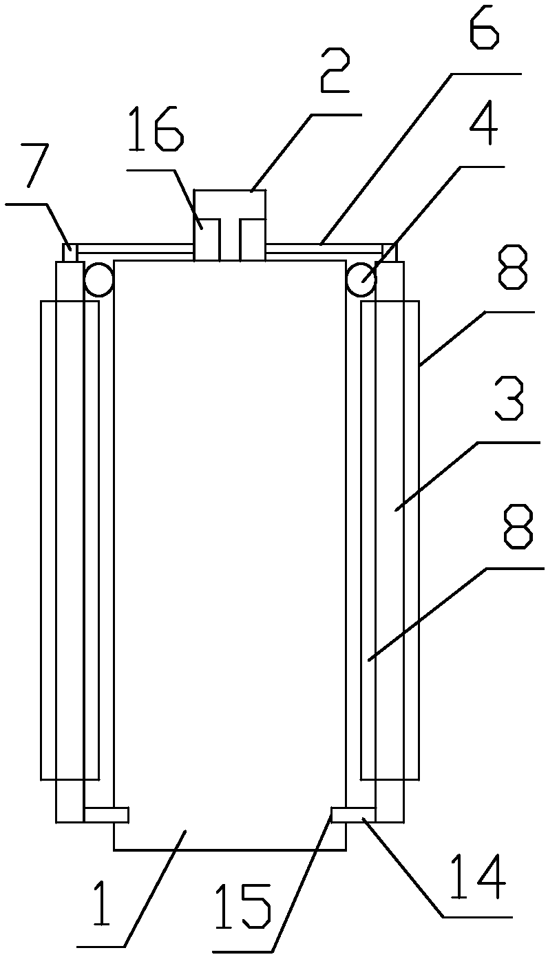
[0037] Further improvement on the basis of Embodiment 2, a positioning block 14 is provided on the end of the mounting plate 3 away from the rotating shaft 4 , and a positioning groove 15 that transition fits with the positioning block 14 is provided on the side of the fixed column 1 near the bottom end in the axial direction. A return spring is set on the rotating shaft 4. When the return spring is in a natural state, the direction of the mounting plate 3 is perpendicular to the side of the fixed column 1. When the mounting plate 3 is turned downward, the other end of the long axis is close to the fixed column 1. When the side wall is closed, the return spring is compressed. The installation housing 2 is provided with a motor 16 adapted to the telescopic rod 6 , and the motor 16 is used to drive the telescopic movement of the telescopic rod 6 . The bottom of the fixed column 1 is provided with several universal wheels.


PUM


Abstract

The invention discloses an efficient solar conversion photovoltaic power generation system. A mounting shell is arranged at the axial top of a regular polygon fixed column, a mounting plate is correspondingly mounted on each side surface of the fixed column, the lower plate surface of one end of a long-axis direction of each mounting plate is rotatably connected with the side wall of the fixed column close to the top through a rotating shaft, photovoltaic power generation boards are embedded into grooves in the mounting plates, one axial end of each telescopic rod is fixed in the mounting shell, the other end of the telescopic rod is connected with the upper plate surface of one end of the long-axis direction of the corresponding mounting plate through a universal joint, positioning stripsare convexly arranged on two sides of the upper plate surface of each mounting plate along a long-axis direction, clamping grooves are formed in the opposite side walls of the two positioning strips,the system comprises protective plates, and each protective plate is clamped between the clamping grooves in the two positioning strips in a transition fitting manner and used for shielding and protecting the corresponding photovoltaic power generation board. A photovoltaic power generation device is convenient to carry and operate.

Description

technical field [0001] The invention relates to the field of photovoltaic technology, in particular to a high-efficiency solar energy conversion photovoltaic power generation system. Background technique [0002] Photovoltaic, short for solar photovoltaic power generation system, is a new type of power generation system that uses the photovoltaic effect of solar cell semiconductor materials to directly convert solar radiation energy into electrical energy. There are two modes of independent operation and grid-connected operation. The classification of solar photovoltaic power generation systems, one is centralized, such as large-scale Northwest ground photovoltaic power generation systems; the other is distributed (with >6MW as the boundary), such as industrial and commercial enterprise factory roof photovoltaic power generation systems, residential roof photovoltaic power generation systems. [0003] The existing solar photovoltaic power generation panels have the follow...

Claims


Application Information

Patent Timeline
Patent Type & Authority Applications(China)
IPC IPC(8): H02S10/40H02S40/42H02S20/30
CPCH02S10/40H02S20/30H02S40/42Y02E10/50
Inventor 张博邢朝路黄帅丛伟伦
Owner 成都亿伏科技有限公司
Why Eureka
Try Eureka