A high-order optical carrier suppression single-sideband signal generation unit and its implementation method

A signal generation unit and optical carrier technology, applied in the field of microwave photonics, can solve the problem of not being able to generate multi-carrier frequency signals, and achieve the effect of simple and flexible implementation method

Active Publication Date: 2019-10-18
XIAN INSTITUE OF SPACE RADIO TECH
View PDF7 Cites 0 Cited by
  • Summary
  • Abstract
  • Description
  • Claims
  • Application Information

AI Technical Summary

Problems solved by technology

At present, the high-frequency local oscillator signal generated by electronic technology is mainly generated by frequency multiplication. Due to the limitation of the electronic device itself, it cannot generate multi-carrier frequency signals with a frequency interval of 50 GHz or even higher.

Method used


Image

  • A high-order optical carrier suppression single-sideband signal generation unit and its implementation method
  • A high-order optical carrier suppression single-sideband signal generation unit and its implementation method
  • A high-order optical carrier suppression single-sideband signal generation unit and its implementation method

Examples


specific Embodiment approach 1

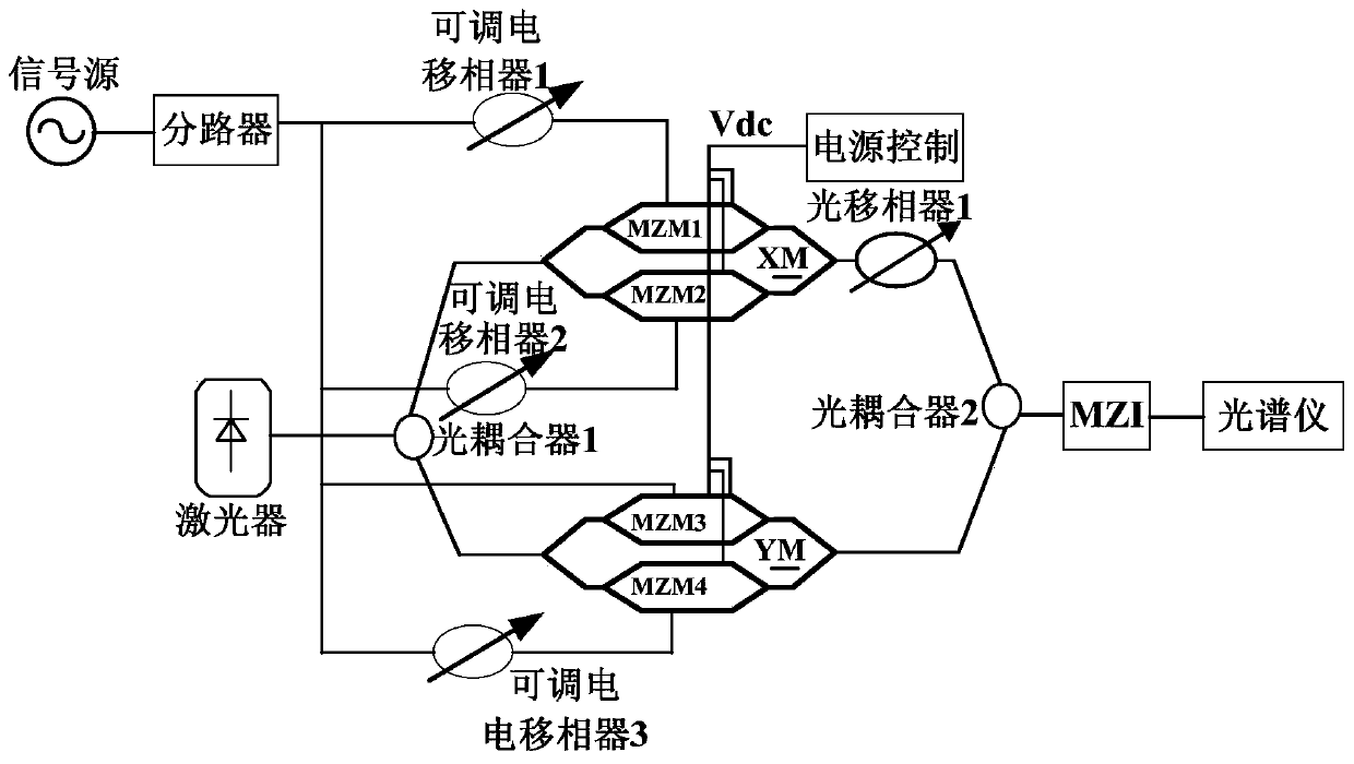
[0027] The first embodiment is a high-order optical carrier suppression single-sideband signal generation method with optional order, such as figure 1shown. Mainly consists of laser, splitter, power control unit, parallel arrangement of DPMZM modulators (XM and YM), adjustable electrical phase shifter 1, adjustable electrical phase shifter 2, adjustable electrical phase shifter 3, optical phase shifter device, optocoupler 1, optocoupler 2 and MZI. Wherein, the laser is divided into two paths through the optical coupler 1 and connected to the input ports of the uplink XM and YM respectively, and the uplink DPMZM (ie XM) includes two sub-modulators (MZM1 and MZM2) and a main modulator, The downlink DPMZM (that is, YM) includes two sub-modulators (MZM3 and MZM4) and a main modulator; the MZM1, MZM2, MZM3 and MZM4 use a single MZM electro-optic modulation effect to perform electro-optic modulation on the input radio frequency electrical signal; After the main modulator controls ...

specific Embodiment approach 2

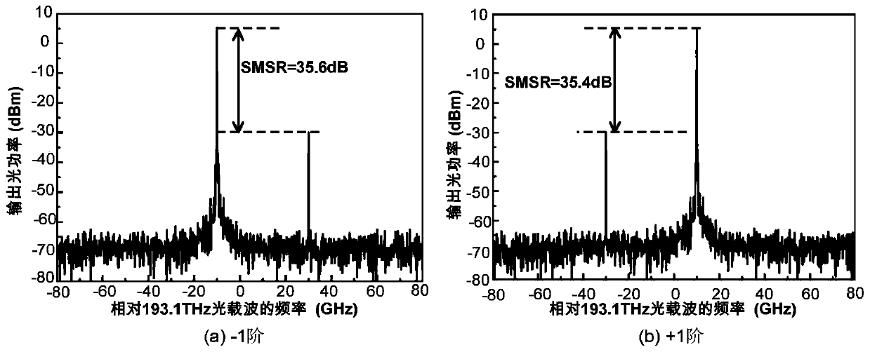
[0032] The second specific embodiment is the first-order optical carrier suppression single sideband signal generation with high sideband suppression ratio, such as figure 1 shown. The specific steps are:

[0033] Step 1: According to figure 1 , the continuous optical signal output by the laser is divided into two paths by the optocoupler 1 and sent to the optical input port of the DPMZM (that is, XM and YM) arranged in parallel, and the excitation signal output by the signal source is divided into four paths by the splitter, respectively Loads to the four RF input ports of sub-modulators MZM1, MZM2, MZM3 and MZM4 of XM and YM. The phase difference of the RF signals loaded on the driving electrodes of the upper and lower arms of the MZM1 is 90 degrees, and the phase difference is realized by the 90-degree adjustable electric phase shifter 1 . The phase difference of the radio frequency signal loaded on the driving electrodes of the upper and lower arms of the MZM2 is -90 de...

specific Embodiment approach 3

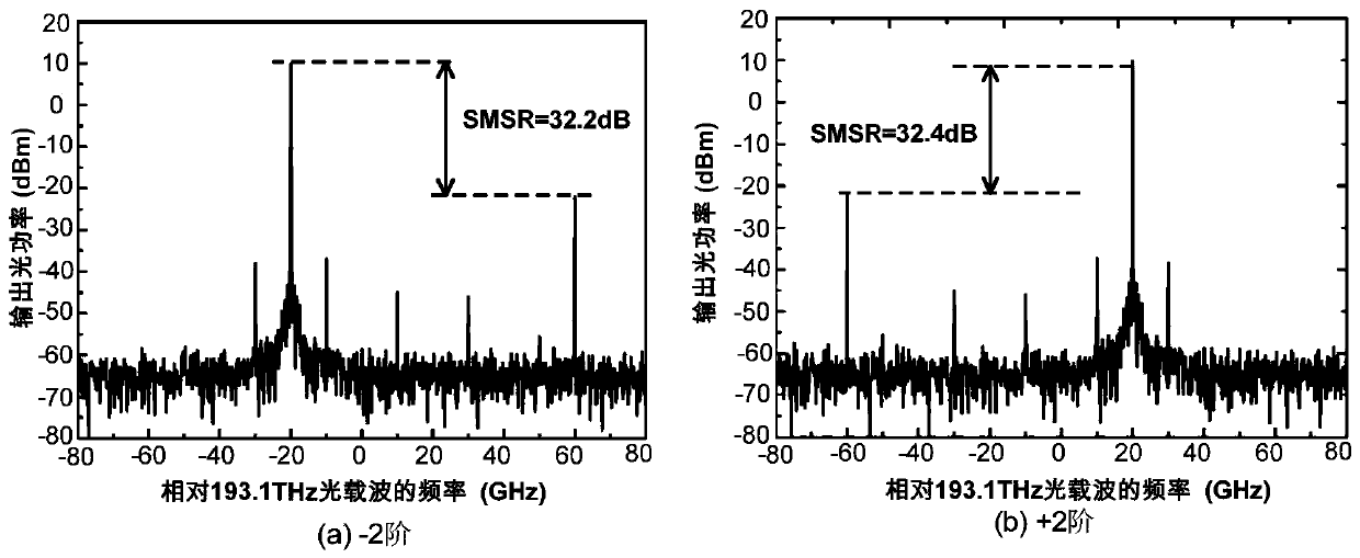
[0042] The third specific embodiment is the second-order optical carrier suppression single sideband signal generation with high sideband suppression ratio, such as figure 1 shown. The specific steps are:

[0043] Step 1: According to figure 1 , the continuous optical signal output by the laser is divided into two channels by the optical coupler 1 and sent to the optical input port of the DPMZM (that is, XM and YM) arranged in parallel, and the excitation signal output by the signal source is divided into four channels after the splitter, respectively loaded Four RF input ports to sub-modulators MZM1, MZM2, MZM3 and MZM4 of XM and YM. The phase difference of the RF signal loaded on the driving electrodes of the upper and lower arms of MZM1 is 45 degrees, which is realized by the 45-degree adjustable electric phase shifter 1 . The phase difference of the radio frequency signal loaded on the driving electrodes of the upper and lower arms of the MZM2 is -45 degrees, and the ph...


PUM


Abstract

The invention relates to a high-order optical carrier inhibition single-side band signal generation unit and an implementation method; the unit comprises a laser, a splitter, an uplink DPMZM modulatorXM, a downlink DPMZM modulator YM, a first adjustable electric phase shifter, a second adjustable electric phase shifter, a third adjustable electric phase shifter, an optical phase shifter, a firstoptical coupler, a second optical coupler and an MZI; according to the working state parameters and the method provided by the invention, direct current bias point control is performed by a single power supply in a unified mode, so that the DPMZMs arranged in parallel work in different modulation states, and an externally applied tunable electric phase shifter, an MZI and an excitation signal areassisted in unified amplitude control; single-side band signals inhibited by a first-order optical carrier, a second-order optical carrier and a third-order optical carrier are generated as required,and the side band inhibition ratio is superior to 30 dB. When the single-side band signals are used for an optical frequency comb based a cycle frequency shift loop, the maximum frequency span can reach three times the bandwidth of the modulator.

Description

technical field [0001] The invention relates to a high-order optical carrier suppression single sideband signal generation unit and a realization method, belonging to the field of microwave photon technology. Background technique [0002] With the development of high-speed and large-capacity requirements of modern communication systems, multi-carrier signal generation units have become an indispensable part. At present, the high-frequency local oscillator signals generated by electronic technology are mainly generated by frequency multiplication. Due to the limitation of electronic devices, it is impossible to generate multi-carrier frequency signals with a frequency interval of 50 GHz or even higher. Microwave photonic technology can realize the generation of multi-carrier frequency signals with wide frequency intervals, and has gradually attracted the attention of researchers as a new technology. [0003] In the microwave photonic multi-carrier frequency technology, the m...

Claims


Application Information

Patent Timeline
Patent Type & Authority Patents(China)
IPC IPC(8): H04B10/516
Inventor 蒋炜秦伟泽谭庆贵赵尚弘李小军梁栋朱忠博
Owner XIAN INSTITUE OF SPACE RADIO TECH
Why Eureka
Try Eureka