Coupling gear spiral rotor pump

A rotor pump and gear technology, applied in the hydraulic field, can solve the problems of gear meshing oil traps, low volumetric efficiency, lack of interchangeability, etc., and achieve the effects of improving overall efficiency, high volumetric efficiency, and improving transmission efficiency

Pending Publication Date: 2018-07-17
SHANXI PINGYANG IND MACHINERY
View PDF0 Cites 3 Cited by
  • Summary
  • Abstract
  • Description
  • Claims
  • Application Information

AI Technical Summary

Problems solved by technology

[0007] 1. There is oil trapped when the gears mesh;
[0008] 2. The working noise of the pump is large;
[0009] 3. The volumetric efficiency of the pump is low;
[0010] 4. Low transmission efficiency;
[0011] 5. Lack of interchangeability

Method used


Image

  • Coupling gear spiral rotor pump
  • Coupling gear spiral rotor pump
  • Coupling gear spiral rotor pump

Examples


Embodiment Construction

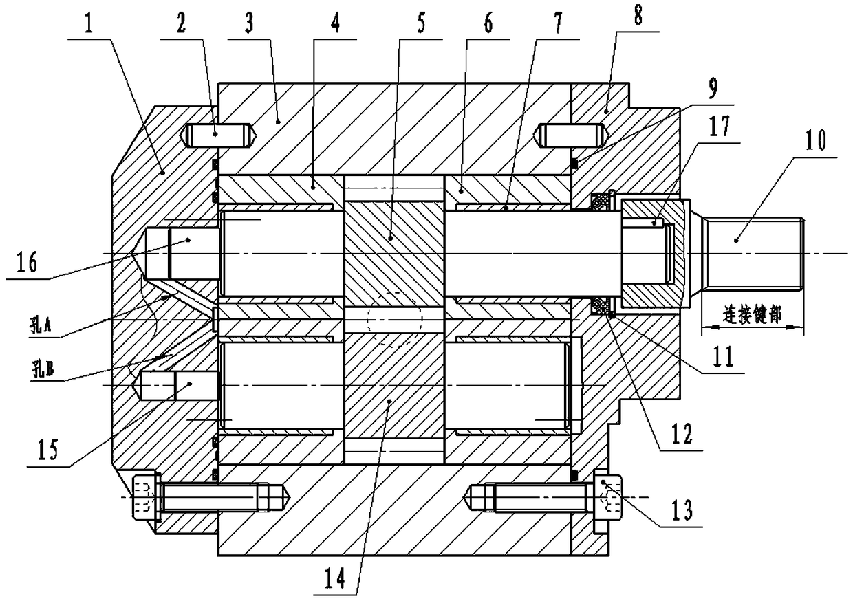
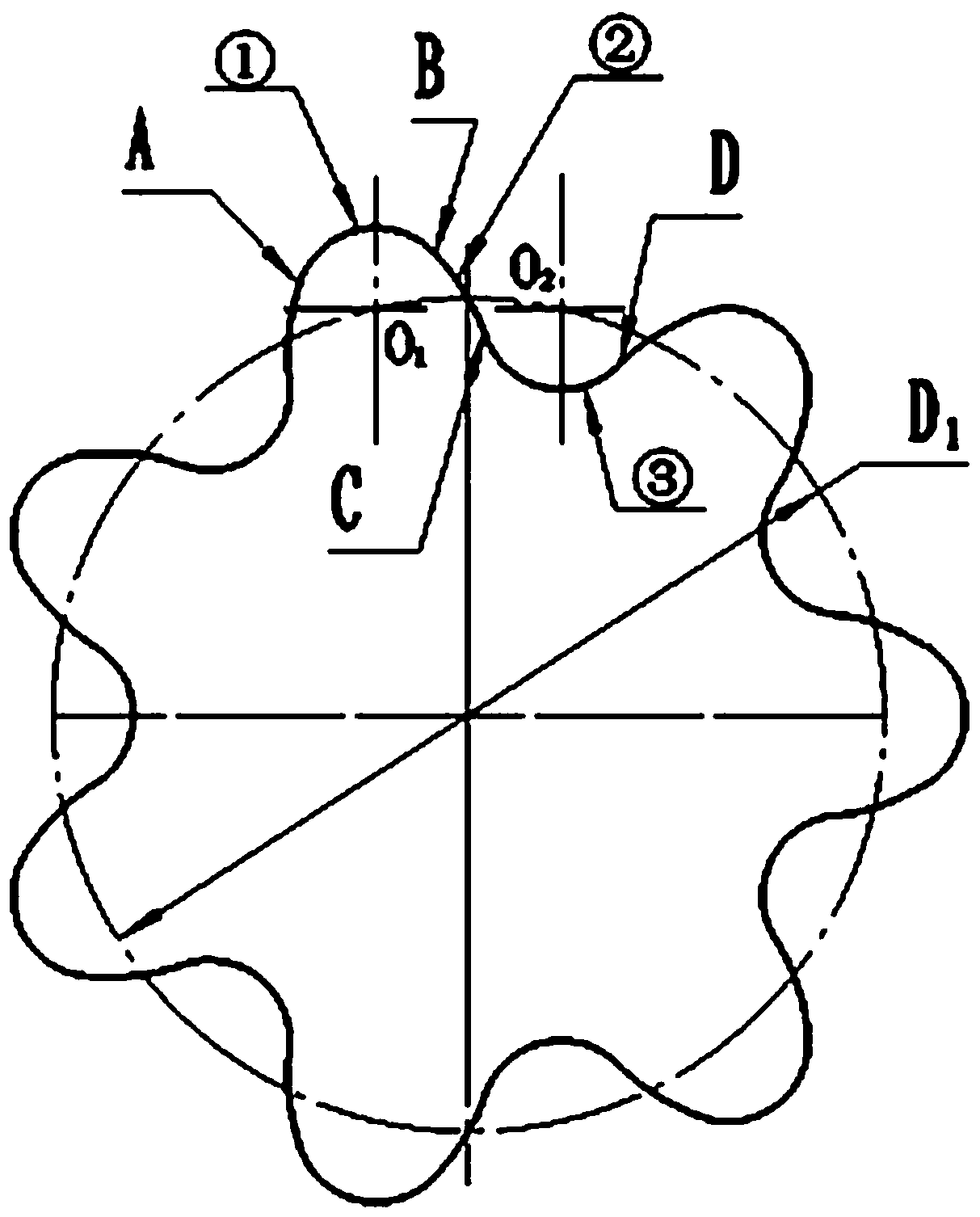
[0037] Technical features and effects of the present invention: 1. The rotor of the pump adopts multi-section coupling curves for tooth profile, and the rotor adopts helical tooth profile design;

[0038] 2. On the end cover where the axial force is directed, the axial force automatic compensation structure design is used to overcome the adverse effects of the axial force;

[0039] 3. The use of DU sliding bearings enables the rotor to move axially, achieving automatic axial clearance compensation and reducing leakage;

[0040] 4. In the radial direction, the mutual self-compression of different materials realizes the balance of forces and achieves the best clearance;

[0041] 5. A transition joint is added at the end of the driving shaft, and the switch between the flat key and the spline can be realized only by improving the transition joint.

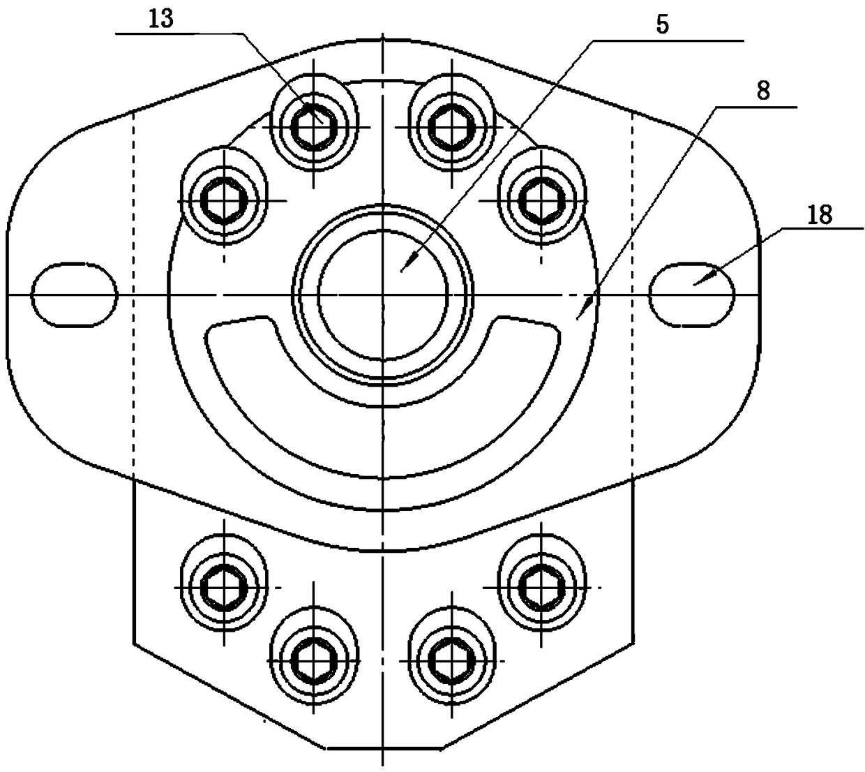
[0042] figure 1 Shown is the overall structure diagram, the main components are: bottom cover 1, positioning pin shaft 2, pump bod...


PUM


Abstract

The invention belongs to the technical field of hydraulic pressure, in particular to a coupling gear spiral rotor pump. The coupling gear spiral rotor pump comprises a pump body, a driving coupling gear shaft, a driven coupling gear shaft, a front pump cover and a bottom cover, wherein the front pump cover and the bottom cover are arranged at the front end and the rear end of the pump body correspondingly. The part, stretching out of the front pump cover, of the driving coupling gear shaft is connected with a transition connector used for being connected with a power element. An involute is used in a gear body part on the driving coupling gear shaft and the driven coupling gear shaft, circular arc curves are adopted at the tooth crest part and the tooth root part to correct the involute, and the connecting positions of the circular arc curves and the involute are in tangent transition. The circle center of the tooth crest circular arc and the circle center of the tooth root circular arc are located on one pitch circle, the two circular arcs are the same in radius, the tooth crest height and the tooth root height of the gear are the same, and rolling friction happens due to contactbetween tooth surfaces in the meshing process. The gear hydraulic pump can achieve the performance of low noise, high volume efficiency and zero-flow pulsation, the tooth service life can be prolonged, and the transmission stability is improved.

Description

technical field [0001] The invention belongs to the field of hydraulic technology, and is a power element suitable for a high-precision hydraulic transmission system, in particular a coupled gear helical rotor pump. Background technique [0002] Gear pump is a commonly used hydraulic pump in modern industry. The traditional gear pump has the advantages of simple structure, convenient manufacture, low price, light weight, small size, reliable operation, etc., but there are also large flow pulsation, difficulty Oil phenomenon, low volumetric efficiency, high noise and other shortcomings. Larger flow pulsation will lead to system pressure pulsation, which will eventually lead to unstable power output of the system. Increase. [0003] Today in the 21st century, fast response, high efficiency, small volume, low noise, low flow pulsation, and large displacement have become necessary requirements for hydraulic transmission systems. As an important power component in the hydraulic...

Claims


Application Information

Patent Timeline
Patent Type & Authority Applications(China)
IPC IPC(8): F04C2/18F04C15/00
CPCF04C2/18F04C15/00F04C2240/20
Inventor 周建勋辛晓敏郑海燕贾敏高啸李鹏
Owner SHANXI PINGYANG IND MACHINERY
Why Eureka
Try Eureka