Aircraft DC power supply system and power supply method

A technology of a power supply system and power supply method, which is applied in the parallel operation of DC power supplies, battery circuit devices, current collectors, etc., can solve the problems of increasing system weight, power loss, and reducing system power density, so as to improve power density and shorten reconfiguration. time, to achieve the effect of continuous power supply

Pending Publication Date: 2018-07-17
BEIJING AERONAUTIC SCI & TECH RES INST OF COMAC +1
View PDF0 Cites 11 Cited by
  • Summary
  • Abstract
  • Description
  • Claims
  • Application Information

AI Technical Summary

Problems solved by technology

[0004] Since the starting input power of the engine starting system is DC power, and the input power reaches 100kW, in order to meet the power demand of the DC power load in the DC power supply system, an AC power conversion device higher than 100kW is required to rectify the high-power AC power into DC power. This increases system weight and reduces system power density
Moreover, due to the difference in frequency and phase angle between the AC power generated by different generators in the AC power supply system, when one of the generators fails, it is necessary to complete the closing action of the contactor between the bus bars to connect the bus bars electrical connection between, thus, causing a temporary loss of electrical energy in the event of a fault

Method used


Image

  • Aircraft DC power supply system and power supply method
  • Aircraft DC power supply system and power supply method
  • Aircraft DC power supply system and power supply method

Examples


Embodiment 1

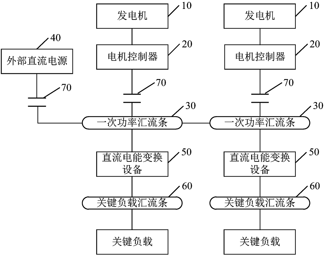
[0023] figure 1 It is a schematic structural diagram of an aircraft DC power supply system provided in Embodiment 1 of the present invention. The aircraft DC power supply system described in this embodiment is suitable for supplying power to aircraft. The system provides a power generation system (including a generator) and motor controller) to the power distribution system (including bus bars and DC power conversion equipment) based on DC power generation and distribution technology. Such as figure 1 As shown, the aircraft DC power supply system described in this embodiment includes:

[0024] At least two engines (not shown in the figure), at least two generators 10 corresponding to the at least two engines (two generators are taken as an example in the figure), and at least two generators 10 correspondingly connected to the at least two generators The motor controller 20 is used to generate and output DC power to the corresponding primary power bus bar 30. The motor contro...

Embodiment 2

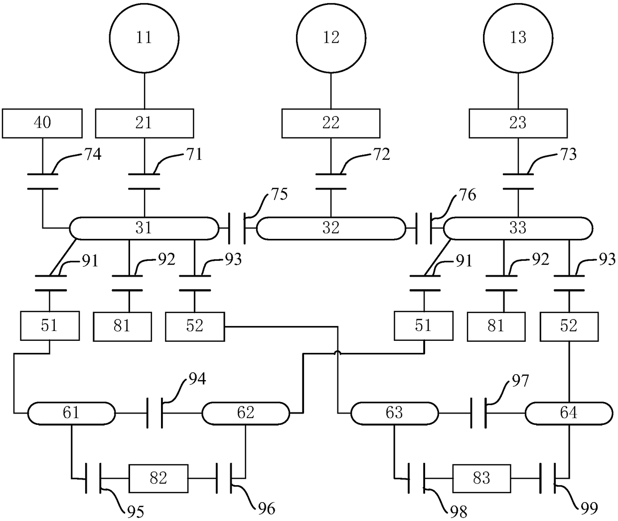
[0044] figure 2 It is a schematic structural diagram of an aircraft DC power supply system provided by Embodiment 2 of the present invention, and this embodiment is a preferred example based on the above embodiments. Such as figure 2 As shown, the aircraft DC power supply system described in this embodiment includes: three engines (not shown in the figure), three generators 11, 12, 13, corresponding to the three generators 11, 12, 13 Three motor controllers 21, 22, 23, and three primary power bus bars 31, 32, 33 respectively corresponding to the three motor controllers 21, 22, 23, and two power transformer devices for converting high-voltage DC power to low-voltage DC power 51, high-voltage DC load 81, two power conversion devices 52 for converting DC power to AC power, two low-voltage DC bus bars 61, 62, two AC bus bars 63, 64, low-voltage DC load 82, AC load 83, external DC A power source 40, and a solid state power controller connected to each electrical device.

[004...

Embodiment 3

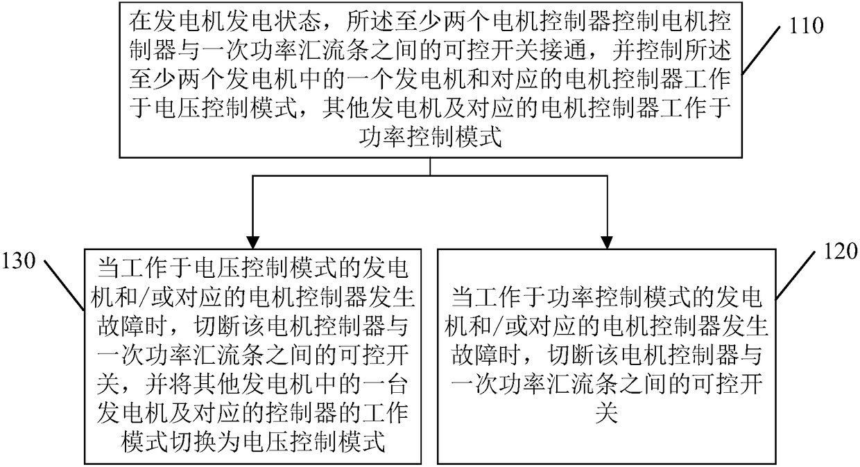
[0054] image 3 It is a flow chart of a power supply method for an aircraft DC power supply system provided in Embodiment 3 of the present invention. This embodiment is applicable to power supply to aircraft, and the method can be executed by the aircraft DC power supply system provided in any embodiment of the present invention. , including the following steps:

[0055] Step 110, in the power generation state of the generator, the at least two motor controllers control the controllable switch between the motor controller and the primary power bus bar to be turned on, and control one of the at least two generators and the The corresponding motor controller works in the voltage control mode, and the other generators and the corresponding motor controllers work in the power control mode.

[0056] Among them, the voltage control mode means that the motor controller uses the output DC voltage value of the generator as a control command to stabilize the output voltage of the gener...


PUM


Abstract

The invention discloses an aircraft DC power supply system and a power supply method. The system comprises: at least two generators and correspondingly connected motor controllers for generating and outputting DC power to corresponding primary power bus bars; at least two primary power bus bars respectively connected to the at least two generators through controllable switches, wherein the two adjacent primary power bus bars are connected to each other; an external DC power source connected to the primary power bus bars through the controllable switches for supplying power to the primary powerbus bars in the engine starting state; DC power conversion devices, wherein the input ends are connected with the primary power bus bars, and the output ends are connected with key load bus bars forconverting the DC power on the primary power bus bars and outputting to the key load bus bars; and the key load bus bars for supplying power to corresponding key loads. The power density of the systemis improved and the continuous power supply of the power supply system when single or multiple generators are faulty is achieved.

Description

technical field [0001] Embodiments of the present invention relate to aircraft power supply technology, in particular to an aircraft DC power supply system and a power supply method. Background technique [0002] Existing aircraft adopt an AC power supply system, that is, a system in which a generator is used to generate three-phase AC power and transmit the three-phase AC power to various electrical loads. The aircraft AC power supply system includes a voltage conversion device, which converts the AC power generated by the generator into various forms of AC power with different voltages and frequencies. At the same time, since the electrical load has the power demand of DC power, for example, the starting system used for engine starting requires DC power as the input power. Therefore, the AC power supply system of the aircraft will also use the AC power conversion device to convert the three-phase AC rectification to DC power. [0003] The aircraft AC power supply system ...

Claims


Application Information

Patent Timeline
Patent Type & Authority Applications(China)
IPC IPC(8): H02J1/10H02J7/34
CPCH02J1/10H02J7/34
Inventor 康元丽回彦年武志勇于贺平王春成王跃
Owner BEIJING AERONAUTIC SCI & TECH RES INST OF COMAC
Why Eureka
Try Eureka