Resin molding apparatus, resin molding method, ejection mechanism, and ejection apparatus

A technology of resin molding and resin, applied in the field of "fluid resin" and resin materials, can solve problems such as inability to discharge liquid resin

Active Publication Date: 2018-07-17
TOWA
View PDF8 Cites 5 Cited by
  • Summary
  • Abstract
  • Description
  • Claims
  • Application Information

AI Technical Summary

Problems solved by technology

When air is mixed into the syringe, there is a problem that the predetermined amount of liquid resin cannot be discharged the next time the liquid resin is discharged

Method used


Image

  • Resin molding apparatus, resin molding method, ejection mechanism, and ejection apparatus
  • Resin molding apparatus, resin molding method, ejection mechanism, and ejection apparatus
  • Resin molding apparatus, resin molding method, ejection mechanism, and ejection apparatus

Examples


Embodiment approach 1

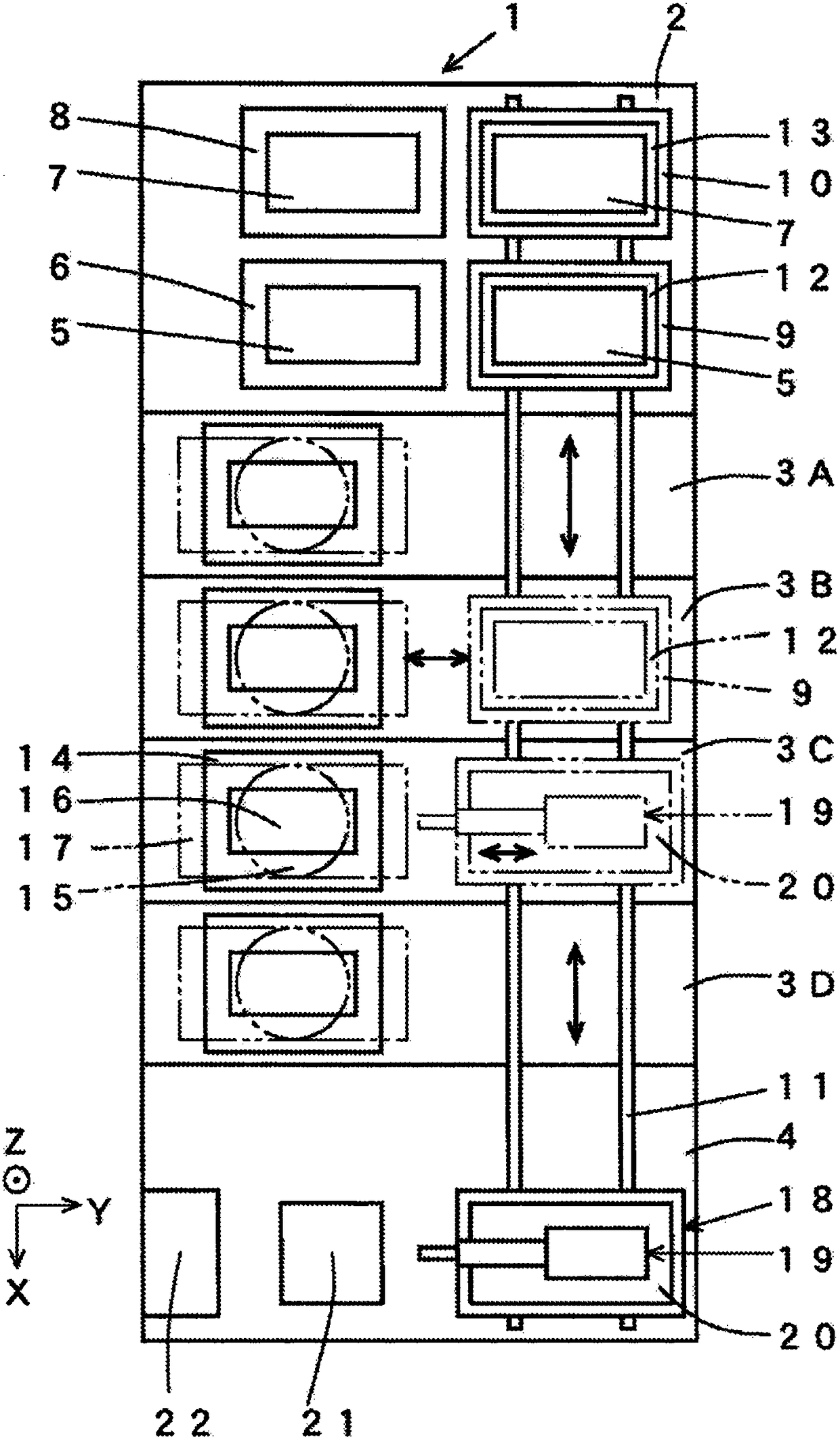
[0043] refer to Figure 1 ~ Figure 4 Embodiment 1 of the resin molding apparatus of this invention is demonstrated. Any of the drawings in this application document are appropriately omitted or exaggerated and schematically drawn for the sake of easy understanding. For the same constituent elements, the same reference numerals are attached and descriptions thereof are appropriately omitted.

[0044] figure 1 The shown resin molding apparatus 1 includes a substrate supply and storage unit 2 , four molding units 3A, 3B, 3C, and 3D, and a supply unit 4 as constituent elements. The substrate supply and storage unit 2, the molding units 3A to 3D, and the supply unit 4 as constituent elements are each detachable from and replaceable with respect to other constituent elements.

[0045] The substrate supply and storage unit 2 is provided with a pre-package substrate supply unit 6 for supplying the pre-package substrate 5 and a packaged substrate storage unit 8 for storing the packa...

Embodiment approach 2

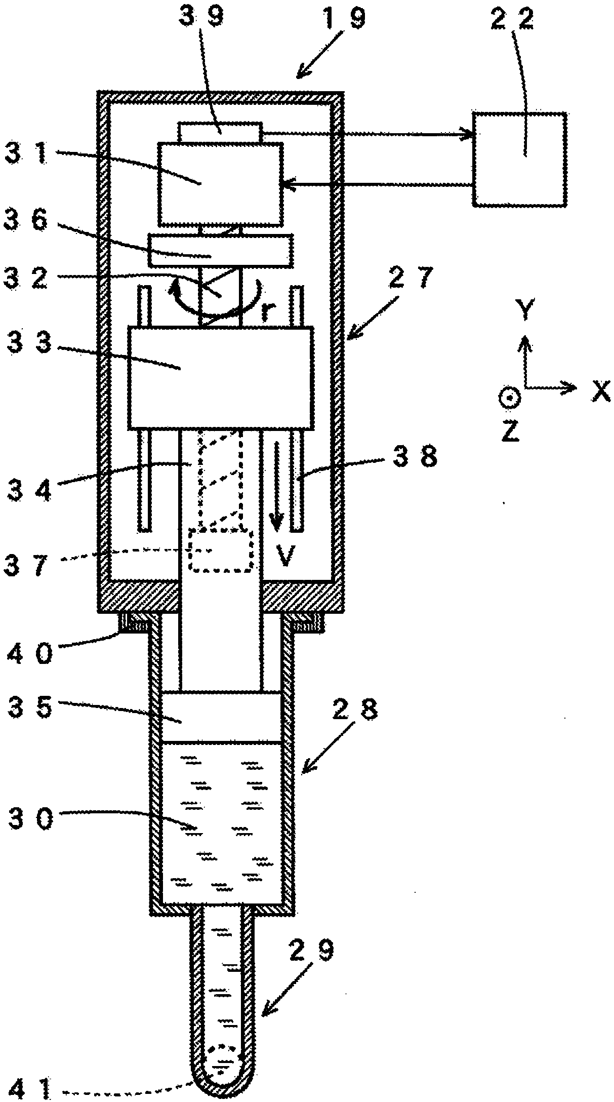
[0097] refer to Figure 5 , using the resin molding apparatus 1 of the present invention, a method of judging whether the liquid resin 30 is normally discharged by monitoring the torque change of the servo motor 31 will be described.

[0098] Figure 5 The torque change of the servo motor 31 in various states of the distributor 19 is shown. The solid line (a) indicates Figure 4 The torque change of the servo motor 31 in the shown normal liquid resin 30 discharge state is shown. The dotted line (b) indicates that during the period during which the plunger 35 pushes the liquid resin 30 (during the period from time point A to time point B2), a predetermined amount of resin is discharged within a predetermined time by making the moving speed V of the plunger 35 constant. Liquid resin 30. However, during the period from the stop of the plunger 35 to the start of sucking back, compared with the normal torque change of the liquid resin 30 represented by the solid line (a), the d...

Embodiment approach 3

[0105] refer to Figure 6 and Figure 7 A description will be given of a method of suppressing sucking of air and dripping of liquid after sucking back by monitoring the torque change of liquid resin 30 after sucking back using the resin molding apparatus 1 of the present invention. Figure 6 Indicates the method of suppressing the inhalation of sucked-back air, Figure 7 Indicates a method for suppressing dripping after sucking back.

[0106] Figure 6 It shows a state where the resin pressure of the liquid resin 30 in the syringe 28 becomes a negative pressure due to the suck back at the time when the suck back is stopped (time point D). At a time (time F) after a certain period of time has elapsed since the suction stop (time D), the resin pressure of the liquid resin 30 in the syringe 28 is still in a negative pressure state. This state is a state in which the resin pressure of the liquid resin 30 becomes excessively negative because the suck-back is too strong relativ...


PUM


Abstract

Provided is a configuration that has a simple construction and has been downsized, and that stably ejects flowable resin. A resin molding apparatus (1) is provided with: a delivery mechanism (27) thatis provided in a supply mechanism (19) and delivers a flowable resin (30); a storage section (28) that is connected to the delivery mechanism and stores the flowable resin; an ejection section (29) that is connected to the storage section and ejects the flowable resin; a rotation mechanism (31) that is provided in the delivery mechanism; a movement member (35) that advances and retreats along aninner wall of the storage section on the basis of rotation of the rotation mechanism, and that pushes the flowable resin stored in the storage section; a detection section (39) that detects a torque value applied to the rotation mechanism via the movement member as a result of resin pressure of the flowable resin inside the storage section; and a control section (22) that controls the movement speed of the movement member or the rotation speed of the rotation mechanism on the basis of the detected torque value. The control unit controls a supply amount of the flowable resin to be supplied to an accommodation section by controlling the movement member to advance, stop, and then retreat.

Description

technical field [0001] The present invention relates to the use of a fluid resin material (hereinafter referred to as "fluid resin") for chip-shaped electronic components such as transistors, integrated circuits (Integrated Circuit: IC) and light emitting diodes (Light Emitting Diode: LED). (Hereinafter referred to as "chip" as appropriate.) A resin molding device and a resin molding method used in the case of resin encapsulation, etc. Furthermore, the present invention relates to a discharge mechanism and a discharge device for discharging a fluid material (hereinafter referred to as "fluid material"). [0002] In this application document, the term "fluidity" means to have fluidity at normal temperature or at a temperature other than normal temperature. The term "liquid state" means that it is liquid and has fluidity at normal temperature. Either of the terms "fluidity" and "liquid state" does not ask about the level of fluidity, in other words, does not ask about the degr...

Claims


Application Information

Patent Timeline
Patent Type & Authority Applications(China)
IPC IPC(8): B29C43/34B29C43/18B29C43/58B29C45/02B29C45/77B29C31/04H01L21/56
CPCB29C31/04B29C45/77B29C43/18B29C43/34B29C43/58B29C45/02H01L21/56H01L21/6715
Inventor 花坂周邦山田哲也岩田康弘后藤智行
Owner TOWA
Why Eureka
Try Eureka