
Vehicle automatic forced speed limit cruise system applicable to speed limit section

A cruise system and adaptive cruise technology, applied to vehicle components, control devices, external condition input parameters, etc., can solve problems such as increasing vehicle fuel consumption and pollutant emissions, damage to vehicle suspension systems, and affecting driver comfort , to achieve the effects of improving fuel economy, avoiding impact damage, and improving driving comfort

Active Publication Date: 2018-07-20
WUHAN UNIV OF TECH
View PDF5 Cites 8 Cited by
  • Summary
  • Abstract
  • Description
  • Claims
  • Application Information

AI Technical Summary

Problems solved by technology

However, in the existing way, the bumps and impacts generated when the vehicle passes through the speed bump often cause damage to the vehicle suspension system and other components, shortening the service life of the vehicle over time, and affecting the comfort of the driver in the vehicle. Noise can also cause disturbance to people who live and work nearby
Some drivers ignore the traffic speed limit signs and adopt sudden braking and rapid acceleration when passing the speed bump, which may easily lead to traffic safety accidents and increase the fuel consumption and pollutant emissions of vehicles
Even if the driver passes the speed reduction belt at a low speed in accordance with the requirements of the traffic regulations, it is still impossible to avoid the impact damage, bumps, noise, etc. of the speed reduction belt on the vehicle.

Method used


Image

  • Vehicle automatic forced speed limit cruise system applicable to speed limit section
  • Vehicle automatic forced speed limit cruise system applicable to speed limit section

Examples


Embodiment Construction

[0033] The present invention will be described in further detail below based on specific embodiments and in conjunction with the accompanying drawings.

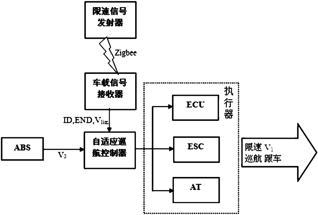
[0034] refer to figure 1 As shown, the vehicle automatic mandatory speed limit cruise system of the speed limit section of the present invention comprises a speed limit signal transmitter (1), a vehicle signal receiver (3), an adaptive cruise controller (2), a vehicle CAN bus (4), actuator (5), wherein:

[0035] The speed limit signal transmitter (1) is designed based on Zigbee wireless communication technology, installed at the beginning and end of the speed limit road section, used to transmit the speed limit signal of the corresponding road section, and order the vehicle to pass the road section within the corresponding speed limit value.

[0036] The vehicle-mounted signal receiver (3) is based on a 32-bit single-chip microcomputer, establishes vehicle-road wireless Zigbee communication with the speed limit signal transmit...


PUM


Abstract

The invention discloses a vehicle automatic forced speed limit cruise system applicable to a speed limit section and is mainly oriented to roads of speed limit parks such as campuses and communities.The system comprises speed limit signal transmitters, an onboard signal receiver, a self-adaptive cruise controller, an onboard CAN bus and an actuator. The speed limit signal transmitters are arranged at the beginning end and the terminal end of the speed limit section and used for wirelessly transmitting a speed limit signal to a vehicle; after the onboard signal receiver receives the signal, the signal is transferred to the self-adaptive cruise controller of the vehicle through the onboard CAN bus, the speed of the vehicle is controlled to gently decrease, and the vehicle is forced to passat a speed lower than the speed limit value; and when the receiver receives a speed limit release signal, it indicates that the vehicle leaves the speed limit section, and the forced speed limit driving state is exited. By applying the vehicle automatic forced speed limit cruise system applicable to the speed limit section, the vehicle-road wireless communication is established, vehicles are forced to run at limited speeds through self-adaptive cruise control both in the manual and automatic driving modes, speed bumps are replaced, damage to vehicle components are avoided, the driving noise inparks is reduced, and safety and riding comfort are enhanced.

Description

technical field [0001] The invention relates to the field of vehicle speed control, in particular to a vehicle-road wireless communication vehicle automatic forced speed limit cruising system for road sections requiring speed limit such as campuses and residential quarters. Background technique [0002] The development of the modern automobile industry has brought great convenience to people's lives, but it has also caused many problems such as traffic safety, noise and emission pollution. Therefore, it is necessary to reasonably coordinate the relationship between people-vehicle-road. Roads in campuses, residential quarters, etc. often have speed limit requirements. The current speed limit method is to remind drivers through traffic speed limit signs, and install speed bumps on speed limit roads to force drivers to slow down and pass, which can play a certain role in speed limit . However, in the existing way, the bumps and impacts generated when the vehicle passes through...

Claims


Application Information

Patent Timeline
Patent Type & Authority Applications(China)
IPC IPC(8): B60W30/14B60W10/06B60W10/10B60W10/188
CPCB60W10/06B60W10/10B60W10/188B60W30/146B60W2556/45B60W2710/0666B60W2710/1005B60W2710/182
Inventor 裴晓飞徐丁辉
Owner WUHAN UNIV OF TECH
Learn More