
Remote monitoring system of gas pipeline

A remote monitoring system, gas pipeline technology, applied in pipeline systems, gas/liquid distribution and storage, mechanical equipment, etc., can solve the problems of time-consuming, labor-intensive, low-efficiency, etc., to improve data backup management, save manpower and material resources, and improve data The effect of access performance

Inactive Publication Date: 2018-07-20
北京东方通捷燃气有限责任公司
View PDF8 Cites 4 Cited by
  • Summary
  • Abstract
  • Description
  • Claims
  • Application Information

AI Technical Summary

Problems solved by technology

[0002] When the gas pipeline is delivered to the user, it is necessary for personnel to go to each household to make statistics and copy reports, and to count the gas flow, which is not only time-consuming and laborious, but also very inefficient

Method used


Image

  • Remote monitoring system of gas pipeline

Examples


Embodiment

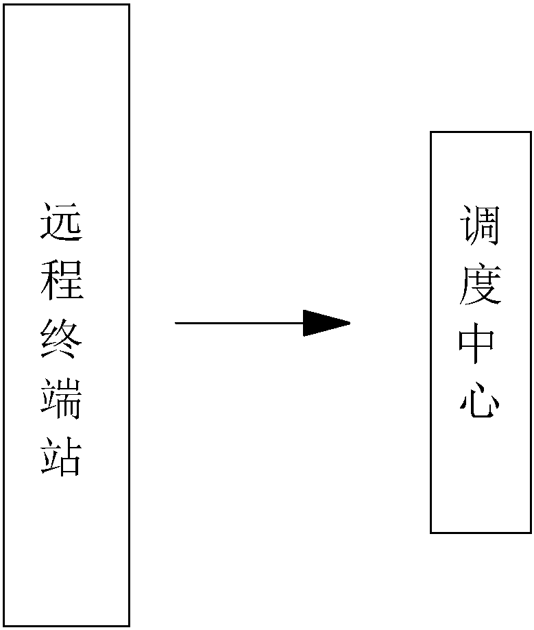
[0024] Embodiment: a gas pipeline remote monitoring system, such as figure 1 As shown, it includes multiple remote terminal stations. The remote terminal stations are distributed in the gas pipeline network or stations, and are used to collect relevant data and calculate the gas flow. Sites include LNG filling stations, gasification stations, user residences, and enterprise workshops.

[0025] After the remote terminal station collects the data and gas flow, it sends it to the dispatching center through the communication system.

[0026] The remote terminal station includes a station control system and monitoring points; the monitoring points are used to collect relevant data of the station, including flow meters, pressure sensors, temperature probes, concentration probes, and infrared probes. The flow meter displays the flow rate of the pipeline, the pressure change sensor feedbacks the pressure in the pipeline in time, the temperature probe and the concentration probe detec...


PUM


Abstract

The invention discloses a remote monitoring system of a gas pipeline. According to the technical scheme, the remote monitoring system of the gas pipeline is characterized by comprising a plurality ofremote terminal stations and a dispatching center, wherein the remote terminal stations are distributed at a pipe network or a site and are used for collecting related data, computing gas flow and sending the collected data and gas flow to the dispatching center through a communication system; and the dispatching center is used for receiving the collected data and gas flow from the remote terminalstations and processing and displaying the collected data and gas flow. The remote monitoring system of the gas pipeline has the advantage that the gas flow of a user can be detected in real time andstatistics is made.

Description

technical field [0001] The invention relates to the field of gas transportation, in particular to a gas pipeline remote monitoring system. Background technique [0002] When the gas pipeline is delivered to the user, it is necessary for personnel to go to each household to make statistics and copy reports, and to count the gas flow, which is not only time-consuming and laborious, but also very inefficient. Therefore, it is necessary to design a remote monitoring system for gas pipelines to monitor the flow of gas. Contents of the invention [0003] The purpose of the present invention is to provide a gas pipeline remote monitoring system, which has the advantage of real-time detection of user gas flow and statistics. [0004] The above-mentioned technical purpose of the present invention is achieved through the following technical solutions: a gas pipeline remote monitoring system, comprising: [0005] The remote terminal station includes a plurality of remote terminal s...

Claims


Application Information

Patent Timeline
Patent Type & Authority Applications(China)
IPC IPC(8): F17D3/01
CPCF17D3/01
Inventor 边学会杨卓然钱文源
Owner 北京东方通捷燃气有限责任公司
Learn More