Angle adjustable firework launching frame

An adjustable, launcher technology, applied in the direction of fireworks, offensive equipment, weapon types, etc., can solve the problems of personal injury, unsafe fireworks, easy to cause danger, etc., to change the launch angle, reduce safety hazards, and improve attention. force effect

Pending Publication Date: 2018-07-20
江西常驰实业有限公司
0 Cites 1 Cited by

AI-Extracted Technical Summary

Problems solved by technology

[0002] Every New Year or major festival, people always set off some fireworks to celebrate. Because there is gunpowder in the fireworks, the ground is uneven, or because the fireworks are left for too long, the internal structure of the firework launch tube is damaged, and it is easy to cause danger when setting off. Therefore, the fire rack came into being
[0003] The common pyrotechnic display stand simply fixes the pyrotechnics, cannot adjust the launch angle, and ha...

Method used

Further, electromagnetic board 15 switches and light box 12 switches are respectively installed on control box 13, and control box 13 is electrically connected electromagnetic board 15 and light box 12 respectively, and the electromagnetic board 15 and light box 12 of electrical connection, make operation The launcher is more convenient and faster.
Further, launch tube 18 has sixteen, and each launch tube 18 apertures are identical, and launch tube 18 is equidistantly arranged in launch box 9, and launch tube 18 apertures are identical, can make the pyrotechnics of filling more when launching Stablize.
Further, stepping motor switch 17 is electrically connected to stepping motor 4, and stepping motor 4 output end rotation angles are three hundred and sixty degrees, and stepping motor 4 output end rotation angles can be three hundred and sixty degrees , to make the adjustment of the launch direction faster, without the need to move the launch stand, which is convenient for operation.
Further, the top of shock absorber 2 is provided with damping plate, and the bottom of shock absorber 2 is provided with fixed support, and shock absorber 2 has four, and its equidistant distribution is in the inside of base 1, is arranged on The shock absorber 2 inside the base 1 unloads the recoil force generated when the py...

Abstract

The invention discloses an angle adjustable firework launching frame. According to the angle adjustable firework launching frame, a stepping motor arranged in a base drives a rotary disc to rotate through rotation of an output shaft, a workbench rotates, and accordingly a launching box can launch fireworks by 360 degrees. A hydraulic jack is arranged on the workbench, a connecting base is arrangedon the top of the hydraulic jack, the connecting base is connected to the launching box through a hinge, the hydraulic jack ascends, the launching box is subjected to traction force of the hydraulicjack, the launching box starts to move in the hydraulic jack direction through a roller arranged at the bottom, and accordingly the launching angle of the launching box is changed. A lamp box is arranged on the workbench, when the fireworks are set off at night, an incandescent lamp in the lamp box is turned on, lighting can be provided for firework set-off persons, neon lamps can warn coming andgoing pedestrians about firework set-off, the attention of the pedestrians is improved, and potential safety hazards are reduced.

Application Domain

Fireworks

Technology Topic

Launch angleAerospace engineering +5

Image

  • Angle adjustable firework launching frame
  • Angle adjustable firework launching frame
  • Angle adjustable firework launching frame

Examples

  • Experimental program(1)

Example Embodiment

[0018] The technical solutions in the embodiments of the present invention will be clearly and completely described below in conjunction with the accompanying drawings in the embodiments of the present invention. Obviously, the described embodiments are only a part of the embodiments of the present invention, rather than all the embodiments. Based on the embodiments of the present invention, all other embodiments obtained by those of ordinary skill in the art without creative work shall fall within the protection scope of the present invention.
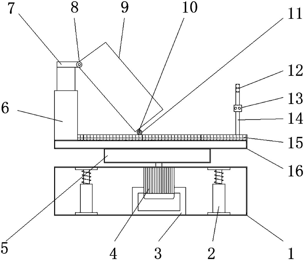
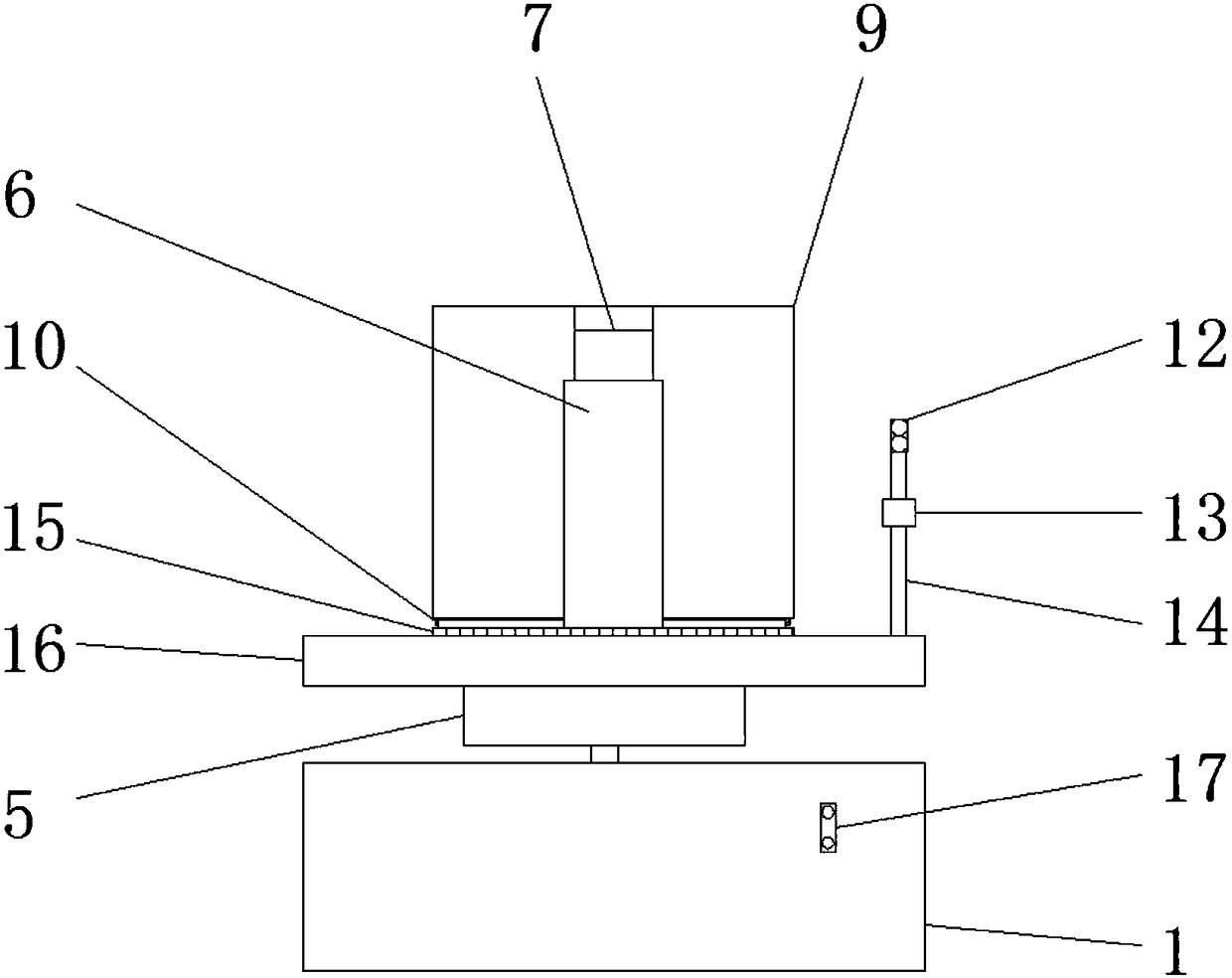
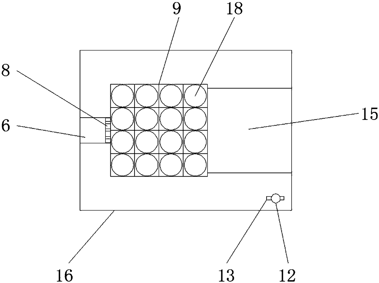
[0019] See Figure 1-3 , The present invention provides a technical solution: including a base 1, a shock absorber 2, a stepping motor mounting seat 3, a stepping motor 4, a turntable 5, a hydraulic jack 6, a connecting seat 7, a hinge 8, a launching box 9, a support rod 10. Roller 11, light box 12, control box 13, lamp post 14, electromagnetic board 15, workbench 16, stepping motor switch 17 and launch tube 18, the inside of base 1 is installed with shock absorber 2 and motor mounting seat 3 respectively The stepping motor mounting seat 3 is equipped with a stepping motor 4, the output end of the stepping motor 4 is connected with a turntable 5, the top of the turntable 5 is connected with a worktable 16, and the top of the worktable 16 is respectively provided with a hydraulic jack 6, a lamp post 14 and the electromagnetic board 15, the top of the hydraulic jack 6 is provided with a connecting seat 7, one end of the top of the connecting seat 7 is connected with a hinge 8, one end of the hinge 8 is connected with a launching box 9, and the launching box 9 is provided with a launching tube 18 inside. The bottom of the box 9 is provided with a support rod 10, one end of the support rod 10 is connected with a roller 11, a light box 12 and a control box 13 are respectively installed on the lamp post 14, and the control box 13 is located directly under the light box 12, one side of the base 1 A stepping motor switch 17 is provided.
[0020] Further, the top of the shock absorber 2 is provided with a shock absorbing plate, and the bottom of the shock absorber 2 is provided with a fixed bracket. There are four shock absorbers 2, and they are equally spaced in the interior of the base 1 and arranged inside the base 1. The shock absorber 2, when the firework is launched, the recoil generated is unloaded, so as to protect the launcher from shaking greatly and make the launch more stable.
[0021] Further, incandescent lamps and neon lamps are respectively installed in the light box 12, and the outer shell of the light box 12 is made of transparent materials. The incandescent lamp can provide lighting for the setter, and the neon lamp can remind passing pedestrians.
[0022] Further, the electromagnetic board 15 switch and the light box 12 switch are respectively installed on the control box 13, and the control box 13 is electrically connected to the electromagnetic board 15 and the light box 12 respectively, and the electromagnetic board 15 and the light box 12 are electrically connected, so that the operation launcher is more Convenient and fast.
[0023] Further, there are sixteen launching tubes 18, each of which has the same aperture, and the launching tubes 18 are arranged equidistantly in the launching box 9. The launching tubes 18 have the same aperture, which can make the filled fireworks more stable during launch.
[0024] Further, the stepping motor switch 17 is electrically connected to the stepping motor 4, and the rotation angle of the output end of the stepping motor 4 is three hundred and sixty degrees, and the rotation angle of the output end of the stepping motor 4 can be three hundred and sixty degrees. The direction adjustment is quicker, no need to move the launcher, easy to operate.
[0025] Further, the two ends of the roller 11 are respectively installed with support rods 10, and the roller 11 is made of iron material, the iron roller 11, when the electromagnetic plate 15 is energized, the roller 11 can be adsorbed on the electromagnetic plate 15 to fix the launch box 9 , Make the launching box 9 launch more stable.
[0026] Working principle: When working, the stepping motor 4 and the output end of the stepping motor 4 set in the base 1 rotate to drive the turntable 5, and the turntable 5 drives the worktable 16 to rotate, thereby changing the direction of the launcher, and is set on the worktable 16. The hydraulic jack 6, the hydraulic jack 6 rises, and drives the launching box 9 connected by hinge to change the launching angle of the launching box 9. The roller 11 at the bottom of the launching box 9 rotates, and the electromagnetic board 15 on the control box 13 is turned on. The electromagnetic board 15 Electricity generates magnetic force, exerting a force on the iron roller 11, thereby fixing the launching box 9, the lamp post 14 arranged on the workbench 16, and the lamp post 14 is respectively provided with a light box 12 and a control box 13, by opening the control box The light box 12 on the 13 switch makes the incandescent lamp work and provides lighting for the fireworks. The shock absorber 2 installed in the base 1 uses its own shock absorption effect to unload the recoil generated when the fireworks are released, thereby protecting The launching frame launches stably to ensure the safety of personnel.
[0027] Although the embodiments of the present invention have been shown and described, those of ordinary skill in the art can understand that various changes, modifications, and substitutions can be made to these embodiments without departing from the principle and spirit of the present invention. And variations, the scope of the present invention is defined by the appended claims and their equivalents.

PUM

no PUM

Description & Claims & Application Information

We can also present the details of the Description, Claims and Application information to help users get a comprehensive understanding of the technical details of the patent, such as background art, summary of invention, brief description of drawings, description of embodiments, and other original content. On the other hand, users can also determine the specific scope of protection of the technology through the list of claims; as well as understand the changes in the life cycle of the technology with the presentation of the patent timeline. Login to view more.

Similar technology patents

Fan blade and rotor integrated brushless direct current motor

PendingCN111446832Aimprove concentrationincrease flow rate
Owner:INNER MONGOLIA AGRICULTURAL UNIVERSITY

Motorcycle totally-closed auxiliary equipment with lighting and warning lamp functions

InactiveCN111645784Aimprove concentrationReduce the probability of car accidents
Owner:JINAN HUIMAN AUTOMOBILE SUPPLIES CO LTD

Safe, non-toxic and fragrant pencil paint and preparation method thereof

InactiveCN106366917AThe production process is simpleimprove concentration
Owner:颍上县满天星文具用品有限公司

Auxiliary learning system and device and answer sheet

PendingCN112527216Aimprove concentrationReduce eyestrain
Owner:XIAMEN INTRETECH

Classification and recommendation of technical efficacy words

  • Reduce security risks
  • improve concentration

Automatic driving system

Owner:CHERY AUTOMOBILE CO LTD

Power safety socket device

ActiveCN106848698AReduce security risksImprove power supply stability
Owner:东莞科奔电器有限公司

Network access authentication method and its USIM card

InactiveCN101123778AReduce security riskslittle change
Owner:DATANG MICROELECTRONICS TECH CO LTD

Bioreactor with mixer and sparger

InactiveUS20090130757A1improve concentration
Owner:PALL TECH UK

Method for sending advisement by visual access control system

InactiveCN102045545Aimprove concentrationlow cost
Owner:SICHUAN CHANGHONG ELECTRIC CO LTD

Furrowing, fertilization and earthing device of rice transplanting synchronous fertilizer applicator

ActiveCN110140483Aavoid damageimprove concentration
Owner:NANJING AGRI MECHANIZATION INST MIN OF AGRI

Human body image multi-attribute classification method based on priori prototype attention mechanism

ActiveCN112418261AStrong filterabilityimprove concentration
Owner:UNIV OF ELECTRONIC SCI & TECH OF CHINA

Reality-augmenting transparent display technology

InactiveCN106444029Aimprove concentrationImprove space and visual comfort
Owner:小卖科技有限公司
Why Eureka
Try Eureka