Arc tube bulb shell shaping method and clamp device for shaping of arc tube bulb shell

An arc tube and chuck technology, which is applied in glass forming, glass re-forming, glass manufacturing equipment and other directions, can solve the problem of the uniformity of the outer diameter of the bulb, the uniformity of the wall thickness, the high symmetry of the bulb, and the high requirements of the bulb. Dimensional consistency and shell symmetry are poor, unable to meet production requirements, etc., to achieve the effects of good symmetry, stable pressure, and convenient processing

Inactive Publication Date: 2018-07-24
SOUTHEAST UNIV
View PDF6 Cites 5 Cited by
  • Summary
  • Abstract
  • Description
  • Claims
  • Application Information

AI Technical Summary

Problems solved by technology

Bulb shell manufacturing methods generally adopt glass tube stacking, mold clamping, and bubbling forming methods. The stacking method is that the ignition head melts the glass tube, one end of the glass tube is fixed, the burner moves, and the other end of the glass tube is fed into the stack, and then in Close the forming mold on the part of the melted glass tube, blow air and bubbles in the glass tube, and the glass tube forms a bulb in the mold. After forming, the bulb has good size consistency, but there are mold marks on the outer wall, and the wall thickness uniformity is poor.
[0003] Another bulb forming method is to use the above-mentioned stacking method. After the stacking is completed, use a wide fire to melt the stacked glass tubes, blow air and bubbles in the glass tubes, control the blowing pressure and time, and the glass tubes will bubble. Forming, this method has no mold impression, and the uniformity of wall thickness is improved, but the size consistency and symmetry of the bulb after forming are poor, and the product qualification rate is low
[0004] In particular, the arc tube of the ultra-high pressure mercury lamp is used as a point light source. When the lamp is ignited, the pressure inside the lamp reaches 20MPa, which requires the wall thickness of the glass tube bulb to be thicker, and the outer diameter of the bulb is consistent, the wall thickness is uniform, and the bulb is symmetrical. The requirements are high, and the above-mentioned process methods and equipment cannot meet the production requirements

Method used


Image

  • Arc tube bulb shell shaping method and clamp device for shaping of arc tube bulb shell
  • Arc tube bulb shell shaping method and clamp device for shaping of arc tube bulb shell
  • Arc tube bulb shell shaping method and clamp device for shaping of arc tube bulb shell

Examples


Embodiment Construction

[0032] The present invention will be further explained below in conjunction with the accompanying drawings and specific embodiments. It should be understood that the following specific embodiments are only used to illustrate the present invention but not to limit the scope of the present invention.

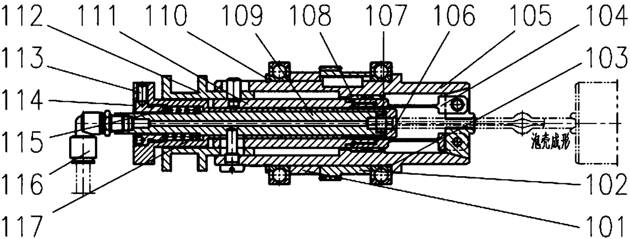
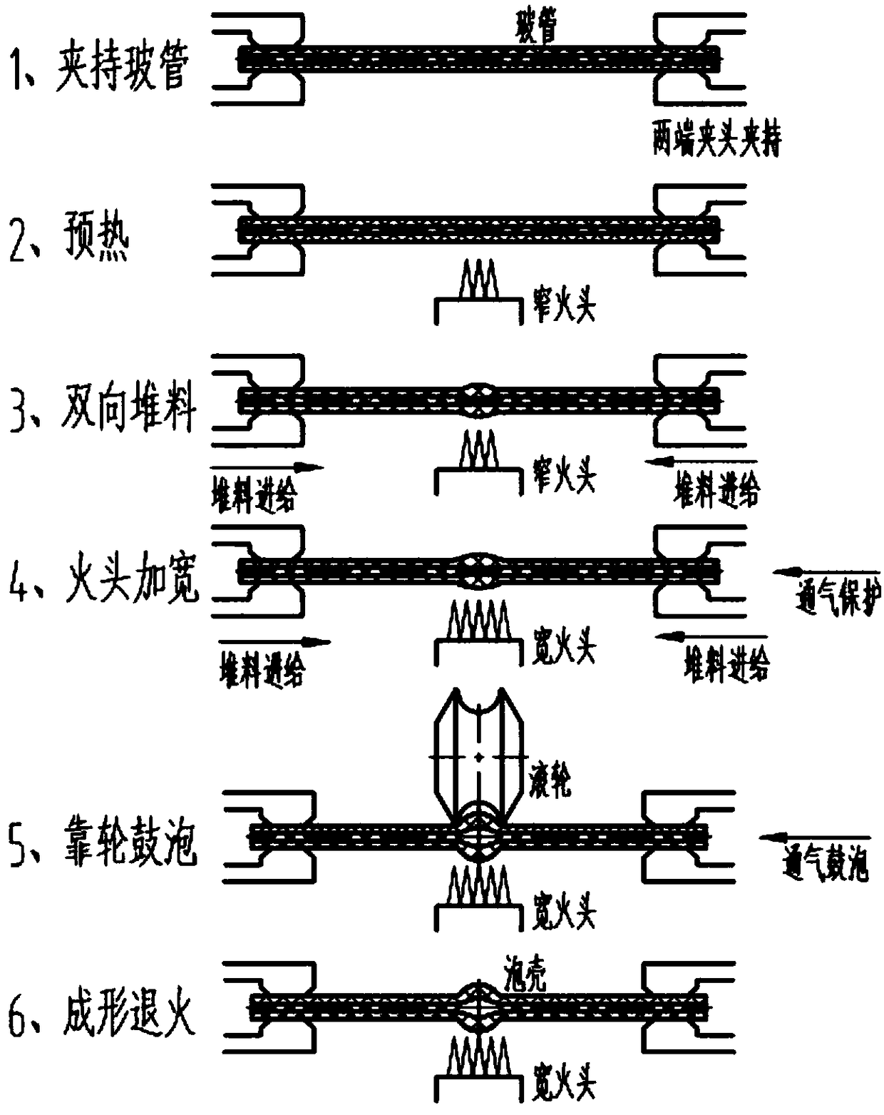
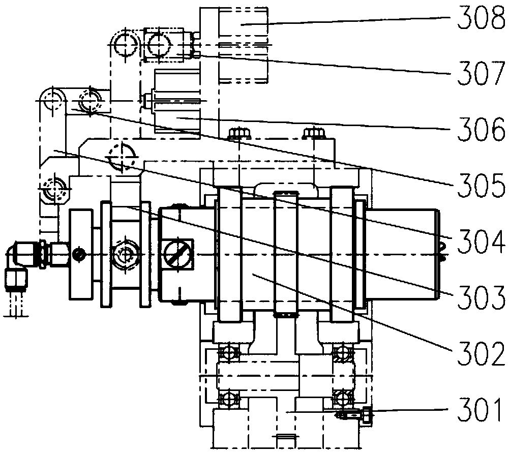
[0033] figure 1 It is an axial sectional view of the chuck device of the present invention, figure 2 It is a process flow diagram of the inventive method, image 3 It is the peripheral structure of the chuck device of the present invention under the use and installation state, Figure 4 is an axial end view of the collet assembly of the present invention, Figure 5 It is a radial cross-sectional view of the positioning pin of the chuck device of the present invention, Image 6 It is the front view of the sleeve of the collet device of the present invention, and the names of the components of the reference signs are in order: 101—spacer, 102—gear, 103—bearing, 104—elastic chuc...


PUM


Abstract

The invention discloses an arc tube bulb shell shaping method and a clamp device for shaping of the arc tube bulb shell. The clamp device comprises an elastic clamp component, a support cylinder and aventilation tube, wherein the end of a glass tube and the ventilation tube are sealed and docked, the glass tube is clamped and fixed through the elastic clamp component, and the support cylinder isconnected with and fixed with the elastic clamp component and the ventilation tube. The method comprises steps of first, clamping the glass tube; second, pre-heating; third, pushing a material in dual-direction; fourth, widening a fire head; fifth, bubbling through a wheel; and sixth, shaping and annealing. After the glass tube is sealed, the impact on glass tube jumping is small, so that the shape and size of the shaped bulb shell are ensured.

Description

technical field [0001] The present invention relates to a chuck device and an arc tube bulb forming method for forming an arc tube bulb, in particular to a processing method for a special light source ultra-high pressure mercury lamp arc tube bulb, an arc tube bulb processed from a quartz glass tube, And the chuck device specially designed for the method belongs to the field of light source technology and equipment technology. Background technique [0002] The bulb of the arc tube of high pressure (ultra-high pressure) gas discharge lamp is made of quartz glass tube. The middle part of the glass tube is processed into a spherical (or ellipsoid) bulb. It is filled with pellets, mercury and gas to become an arc tube. Bulb shell manufacturing methods generally adopt glass tube stacking, mold clamping, and bubbling forming methods. The stacking method is that the ignition head melts the glass tube, one end of the glass tube is fixed, the burner moves, and the other end of the g...

Claims


Application Information

Patent Timeline
Patent Type & Authority Applications(China)
IPC IPC(8): C03B23/07
CPCC03B23/07
Inventor 何荣开贾友彬吕家东刘鹏陈刚
Owner SOUTHEAST UNIV
Why Eureka
Try Eureka