Hydraulic casing centering device

A technology for centralizers and casings, which is applied in the direction of casings, drill pipes, drilling equipment, etc., and can solve problems such as large lowering force, large starting force, and reduced reset force

Active Publication Date: 2018-07-24
STARSE ENERGY & TECH GROUP
View PDF5 Cites 6 Cited by
  • Summary
  • Abstract
  • Description
  • Claims
  • Application Information

AI Technical Summary

Problems solved by technology

[0007] ⑴The elastic righting strip with elastic bending deformation ability can realize the righting effect of the irregular well section on the pipe string; ⑵The lowering force is relatively large; ⑶The starting force is relatively large; ⑷Resetting force is limited and small; The structure improves the fluid flow performance of cement slurry and enhances the displacement efficiency of cement slurry; (6) the application effect is better in conventional wells, but the application in highly deviated wells and horizontal wells is poor, etc.
[0009] ⑴The wellbore trajectory is irregular; ⑵The azimuth angle of the wellbore is constantly changing, resulting in the continuous change of the full angle of the pipe string; It is easy to peel off and collapse; (4) the wellbore produces a large frictional resistance to the pipe string and other properties, so that no matter whether the rigid centralizer or the elastic centralizer is used, there are great shortcomings. For example, the rigid centralizer has: (1) The outer diameter is fixed, The centralizing ability is poor in wells with irregular borehole diameters; (2) the protruding part of the centralizing part is embedded in the wellbore interface, and the wellbore is scratched, causing the wellbore to peel off and collapse; (3) the interaction between the centralizing part of the centralizer and the wellbore interface makes the frictional resistance greater , the pipe string is more difficult to lift or lower; while the elastic centralizer has: (1) lath-type elastic centralizer embedded in the interface of the well wall, scratching the wellbore, causing the well wall to peel off and collapse; (2) the lowering force is compared with Larger in the casing; (3) The starting force is greater than that in the casing (4) The originally small and limited reset force is further reduced; (5) The bearing capacity is insufficient; (6) It cannot be rotated; more impractical

Method used


Image

  • Hydraulic casing centering device
  • Hydraulic casing centering device

Examples


Embodiment Construction

[0060] Below in conjunction with accompanying drawing, structural principle and working principle of the present invention are specifically described:

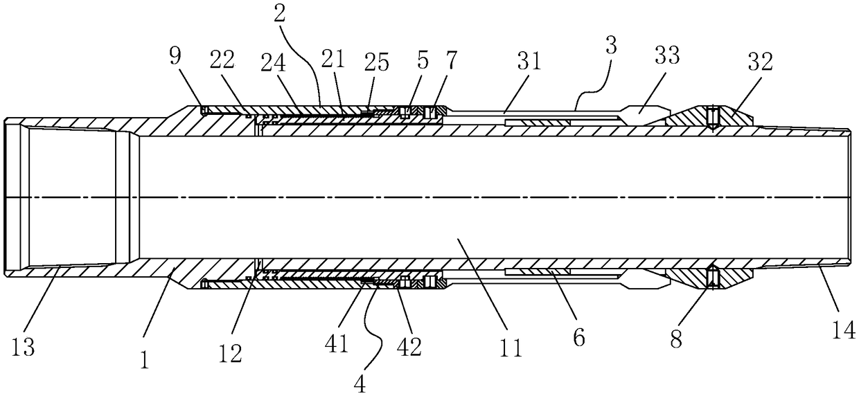
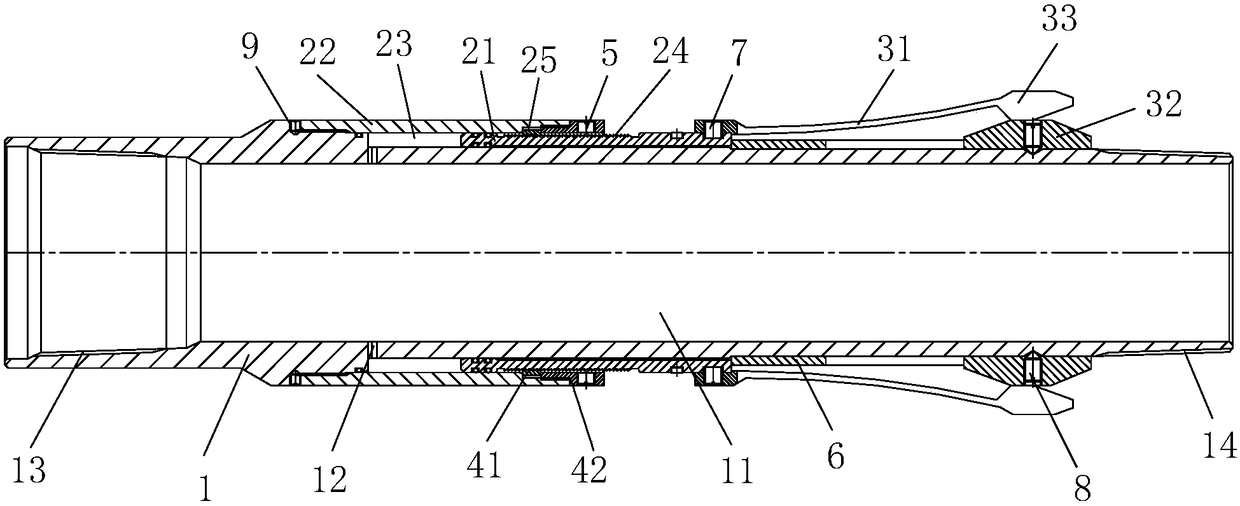
[0061] see figure 1 , figure 1It is a structural schematic diagram of an embodiment of the present invention. The hydraulic casing centralizer of the present invention is used for centering and centralizing the casing in the cementing and completion process, comprising: a body 1, a tubular structural member with a central hole 11, connected to the casing (not shown), preferably The upper end of the body 1 is provided with a female thread 13, and the lower end of the body 1 is provided with a male thread 14, which are respectively used to connect the sleeves at the upper end and the lower end; the driving mechanism 2 includes a piston 21 and a piston cylinder sleeve 22. The piston cylinder liner 22 is set on the body 1 and is fixedly connected with the body 1. There is an accommodating cavity 23 between the piston liner 22 an...


PUM


Abstract

Disclosed is a hydraulic casing centering device used for centering a casing in a well cementing and completion technology. The hydraulic casing centering device comprises a body, a driving mechanismand a centering mechanism, wherein the body is a tubular structural piece provided with a central hole and connected to the casing; the driving mechanism comprises a piston and a piston cylinder sleeve, the piston cylinder sleeve is mounted on the body in a sleeving mode and fixedly connected with the body, an accommodating cavity is formed between the piston cylinder sleeve and the body, the piston is mounted on the body and located in the accommodating cavity, the body is provided with a liquid inlet hole, and the liquid inlet hole communicates with the central hole and the accommodating cavity; and the centering mechanism is mounted on the body and comprises a centering device body and a taper sleeve, one end of the centering device body is connected with the piston, the other end of the centering device body abuts against the taper sleeve, and the taper sleeve is fixed to the body, and the centering device body can climb upwards along the outer conical surface of the taper sleeve.

Description

technical field [0001] The invention relates to a cementing and completion tool for oil drilling, in particular to a hydraulic casing centralizer. Background technique [0002] With the continuous development of directional well (such as highly deviated well, horizontal well) technology, the quality of cementing has become one of the key technical issues affecting the development of directional well technology. To a large extent, the quality of cementing depends on casing or How centered the downhole tool is in the borehole. In directional wells with small inclination angles, the radial component force produced by the weight of the casing itself is small, or even negligible. However, in high-inclination and horizontal directional wells, due to the large inclination The well deviation angle is close to 90°), which results in a large radial component force due to the weight of the casing itself. Or decentralization is difficult, or even stuck. In the cementing project of th...

Claims


Application Information

Patent Timeline
Patent Type & Authority Applications(China)
IPC IPC(8): E21B17/10
CPCE21B17/1014E21B17/1078
Inventor 易会安陈善饮易齐尊马自江李伯仁刘妙仁陈光利
Owner STARSE ENERGY & TECH GROUP
Why Eureka
Try Eureka