
Oil drilling system with drilling fluid in and out

A technology of oil drilling and drilling fluid, which is applied in wellbore/well components, earthwork drilling, flushing wellbore, etc. It can solve problems such as wellbore instability, difficulty, wellbore collapse and block, and improve flowback capacity , The effect of promoting and avoiding material exchange during the drilling process

Active Publication Date: 2020-04-10
CHINA UNIV OF MINING & TECH (BEIJING)
View PDF5 Cites 0 Cited by
  • Summary
  • Abstract
  • Description
  • Claims
  • Application Information

AI Technical Summary

Problems solved by technology

[0002] The narrow drilling fluid density window is likely to cause wellbore instability, leakage reservoir damage and other drilling complications, which seriously restrict the development speed and economic benefits of oil and gas resources
[0003] The problem caused by the narrow drilling fluid density window has brought great difficulty and risk to the actual construction (the density window refers to the density range of the drilling fluid, and the narrow density window is the density range that the drilling fluid can choose during drilling a certain formation. Small, this kind of situation is prone to drilling complex situations, the drilling fluid density exceeds this range and causes lost circulation, and if it is lower than this range, the well wall collapses and blocks)

Method used


Image

  • Oil drilling system with drilling fluid in and out
  • Oil drilling system with drilling fluid in and out
  • Oil drilling system with drilling fluid in and out

Examples


Embodiment Construction

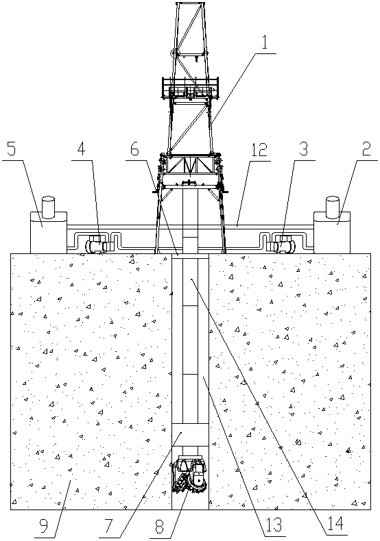
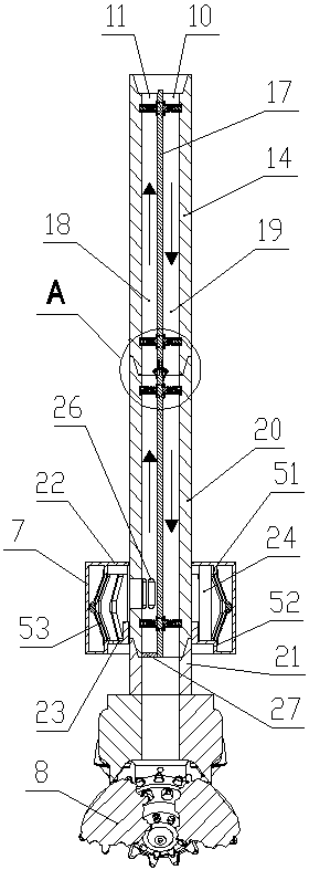
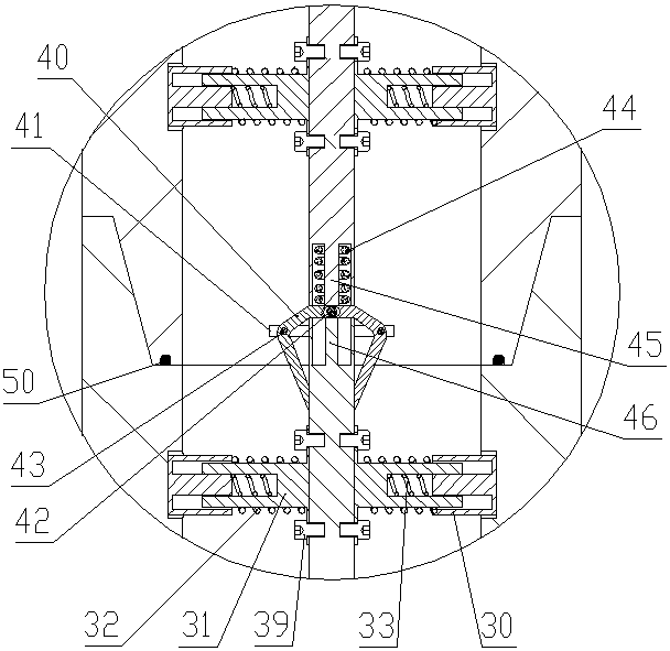
[0032] Such as Figure 1 to Figure 8 shown in figure 2 The left side is the left side of the present invention, figure 2 The direction of the arrow in the figure is the flow direction of the drilling fluid. The oil drilling system of the present invention includes a drilling derrick 1, a drilling fluid inlet tank 2, a drilling fluid booster pump 3, a drilling fluid recovery pump 4, a drilling fluid Liquid recovery tank 5, wellhead blowout preventer 6, drill pipe assembly, formation sealing cylinder 7 and drill bit 8;

[0033]Drilling derrick 1, drilling fluid inlet tank 2, drilling fluid booster pump 3, drilling fluid recovery pump 4 and drilling fluid recovery tank 5 are all fixed on the surface of formation 9. Drilling derrick 1 is provided with a power drive mechanism, and drilling fluid inlet The tank 2, the drilling fluid booster pump 3 and the liquid inlet end 10 of the drill pipe assembly are connected sequentially along the flow direction of the drilling fluid thro...


PUM


Abstract

The invention provides a petroleum drilling system for inside-input and inside-output type drilling fluid. The petroleum drilling system comprises a drilling derrick, a drilling fluid inlet tank, a drilling fluid pressurization pump, a drilling fluid recovery pump, a drilling fluid recovery tank, a wellhead blowout preventer, a drill rod assembly, a stratum sealing drum and a drill bit, wherein the drill rod assembly comprises a plurality of drill rod units which are sequentially connected; a drill rod clapboard is arranged inside each drill rod unit; the front and rear side edges of each drill rod clapboard are in sealed contact with the inner wall of each drill rod unit; each drill rod clapboard is fixed in each drill rod unit through a clapboard fixing assembly; the drill rod clapboardsarranged in different drill rod units are connected through clapboard connecting assemblies; and the interior of the drill rod assembly is divided into a left drilling fluid output channel and a right drilling fluid input channel by the drill rod clapboards. The petroleum drilling system provided by the invention has the advantages that under the action of the drilling fluid recovery pump and thedrilling fluid pressurization pump, the input and output of the drilling fluid can be completed inside the drill rod assembly so as to avoid massive loss of the drilling fluid, and simultaneously, the drilling fluid is circularly utilized so as to lower the drilling cost.

Description

technical field [0001] The invention belongs to the field of oil drilling and relates to a drilling fluid in-in and in-out oil drilling system. Background technique [0002] The narrow drilling fluid density window is likely to cause wellbore instability, leakage reservoir damage and other drilling complications, which seriously restrict the development speed and economic benefits of oil and gas resources. [0003] The problem caused by the narrow drilling fluid density window has brought great difficulty and risk to the actual construction (the density window refers to the density range of the drilling fluid, and the narrow density window is the density range that the drilling fluid can choose in the process of drilling a certain formation. If the density of the drilling fluid exceeds this range, lost circulation will occur, and if the density of the drilling fluid exceeds this range, the well wall will collapse and lose blocks). The factors affecting the drilling fluid de...

Claims


Application Information

Patent Timeline
Patent Type & Authority Patents(China)
IPC IPC(8): E21B43/00E21B21/00E21B21/06E21B33/12
CPCE21B21/00E21B21/06E21B33/12E21B43/00
Inventor 李勇孟尚志吴鹏王壮森
Owner CHINA UNIV OF MINING & TECH (BEIJING)
Learn More