Line fault monitoring method, device, computer readable storage medium and device
A line fault and line technology, applied in the field of electric power, can solve the problems of safe operation of equipment and hidden dangers of power consumption for users, and achieve the effects of avoiding long-term operation with faults, ensuring safe operation, and reducing work intensity
- Summary
- Abstract
- Description
- Claims
- Application Information
AI Technical Summary
Problems solved by technology
Method used
Image

Examples
Embodiment 1
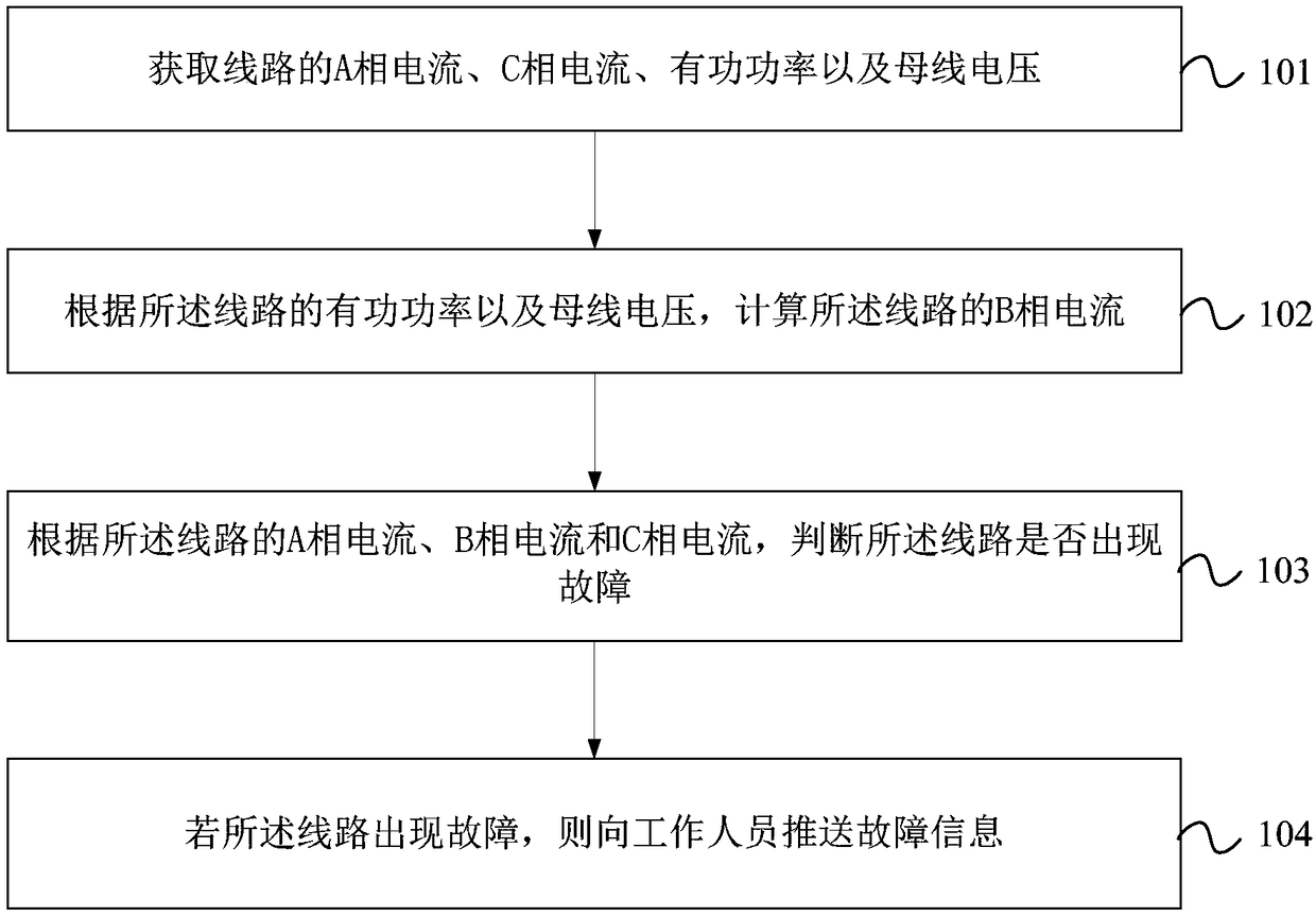
[0063] Embodiment 1 of the present invention provides a line fault monitoring method. figure 1 It is a flow chart of the line fault monitoring method provided by Embodiment 1 of the present invention. Such as figure 1 As shown, the line fault monitoring method in this embodiment may include:
[0064] Step 101. Obtain phase A current, phase C current, active power and bus voltage of the line.
[0065]The line fault monitoring method in this embodiment can be implemented on the basis of the smart grid dispatching control system (D5000 system).
[0066] Specifically, obtaining the A-phase current, C-phase current, active power, and bus voltage of the line may include: collecting real-time data of the line through the measuring device at the station end in the D5000 system; extracting the line from the real-time data of the line A-phase current, C-phase current, active power and bus voltage.
[0067] The implementation method for the D5000 system to collect real-time data of t...
Embodiment 2
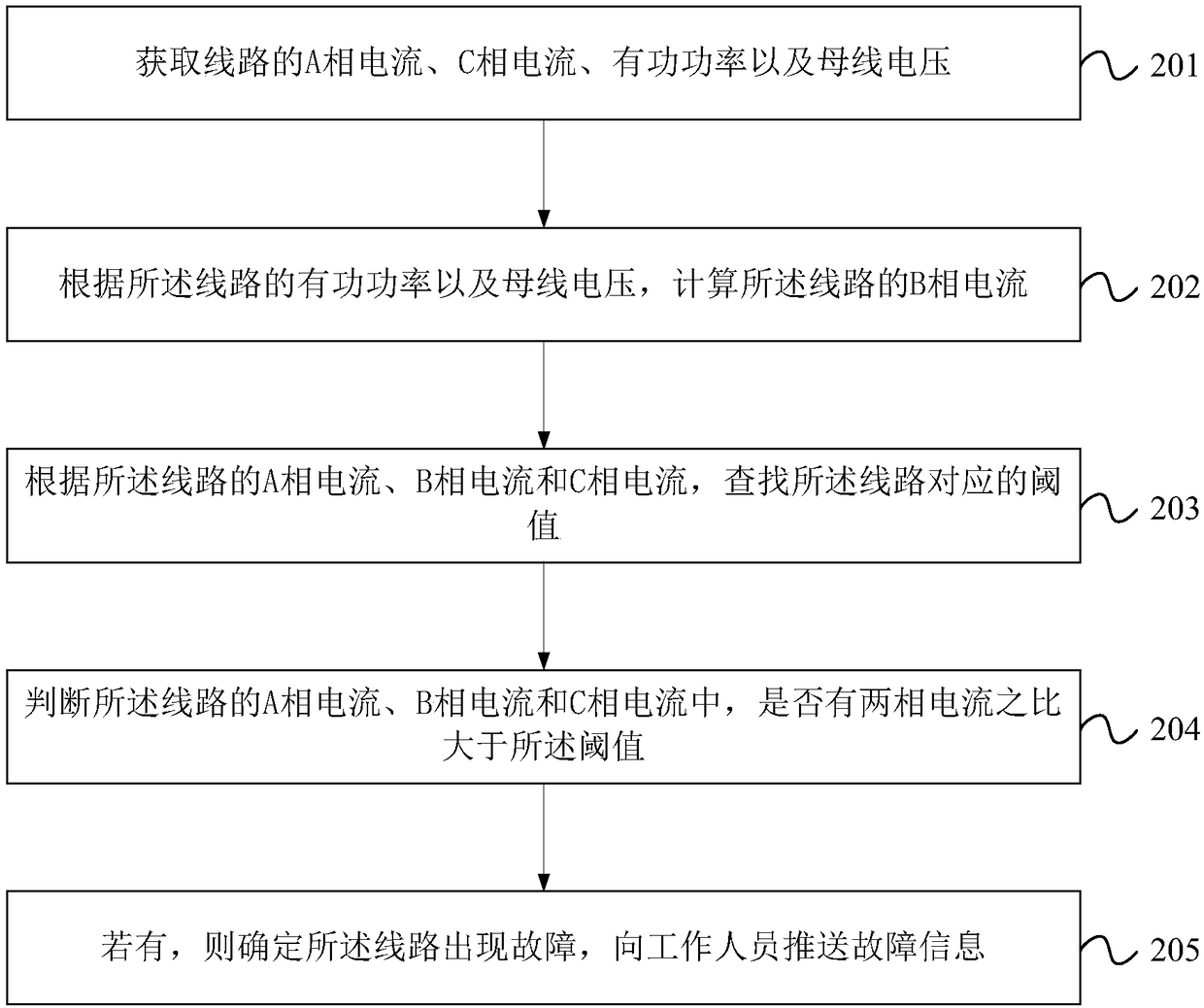
[0095] Embodiment 2 of the present invention provides a line fault monitoring method. In this embodiment, on the basis of the technical solution provided in Embodiment 1, the threshold is determined according to the magnitude of the current.
[0096] figure 2 It is a flow chart of the line fault monitoring method provided by Embodiment 2 of the present invention. Such as figure 2 As shown, the line fault monitoring method in this embodiment may include:
[0097] Step 201 , acquiring phase A current, phase C current, active power and bus voltage of the line.
[0098] Step 202. Calculate the B-phase current of the line according to the active power of the line and the bus voltage.
[0099] In this embodiment, the specific implementation principles of steps 201 to 202 are similar to those of steps 101 to 102 in Embodiment 1, and will not be repeated here.
[0100] Step 203 , according to the A-phase current, B-phase current and C-phase current of the line, search for the t...
Embodiment 3
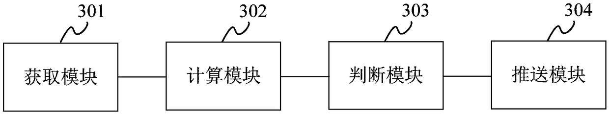
[0109] Embodiment 3 of the present invention provides a line fault monitoring device. image 3 A structural block diagram of a line fault monitoring device provided by Embodiment 3 of the present invention. Such as image 3 As shown, the line fault monitoring device in this embodiment may include:
[0110] An acquisition module 301, configured to acquire the A-phase current, C-phase current, active power and bus voltage of the line;
[0111] A calculation module 302, configured to calculate the B-phase current of the line according to the active power of the line and the bus voltage;
[0112] A judging module 303, configured to judge whether a fault occurs in the line according to the A-phase current, B-phase current, and C-phase current of the line;
[0113] Push module 304, configured to push fault information to staff when the line fails.
[0114] The line fault monitoring device in this embodiment can be used to implement the line fault monitoring method described in any...
PUM
 Abstract
Description
Claims
Application Information
 - R&D
- Intellectual Property
- Life Sciences
- Materials
- Tech Scout
- Unparalleled Data Quality
- Higher Quality Content
- 60% Fewer Hallucinations
Browse by: Latest US Patents, China's latest patents, Technical Efficacy Thesaurus, Application Domain, Technology Topic, Popular Technical Reports.
© 2025 PatSnap. All rights reserved.Legal|Privacy policy|Modern Slavery Act Transparency Statement|Sitemap|About US| Contact US: help@patsnap.com