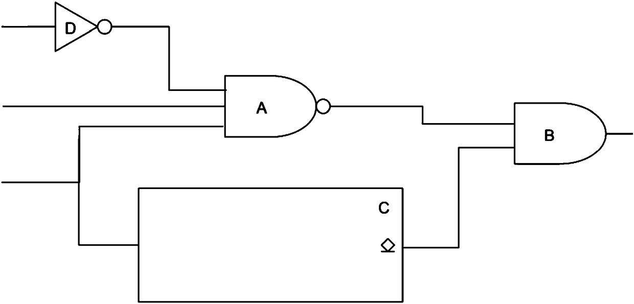
Power supply enable circuit

A power enabling and circuit technology, applied in the field of power supply, can solve problems such as the inability to activate the main system of electronic equipment

Pending Publication Date: 2018-07-24
SHENZHEN MENTAL FLOW TECH CO LTD
View PDF0 Cites 4 Cited by
  • Summary
  • Abstract
  • Description
  • Claims
  • Application Information

AI Technical Summary

Problems solved by technology

[0005] The main purpose of the present invention is to provide a power enabling circuit, which aims to solve the technical probl...

Method used


Image

  • Power supply enable circuit

Examples


Embodiment Construction

[0028] The technical solutions in the embodiments of the present invention will be clearly and completely described below with reference to the accompanying drawings in the embodiments of the present invention. Obviously, the described embodiments are only a part of the embodiments of the present invention, not all of the embodiments. Based on the embodiments of the present invention, all other embodiments obtained by those of ordinary skill in the art without creative efforts shall fall within the protection scope of the present invention.

[0029] It should be noted that all directional indications (such as up, down, left, right, front, back, etc.) in the embodiments of the present invention are only used to explain the relationship between various components under a certain posture (as shown in the accompanying drawings). The relative positional relationship, the movement situation, etc., if the specific posture changes, the directional indication also changes accordingly. ...


PUM


Abstract

The invention discloses a power supply enable circuit. The power supply enable circuit comprises a multi-input nand gate and a delaying circuit, wherein the input end of the multi-input nand gate is connected with multiple channels of activation signals; the input end of the delaying circuit is connected to one path of the activation signals; and the output end of the delaying circuit is wired-andwith the output end of the multi-input nand gate and then is connected to the enable input end of a controlled power supply circuit. According to the power supply enable circuit disclosed by the invention, when any path of the multi-channel activation signals is logic 0, the power supply circuit is activated by the circuit and thereby a main system of a corresponding electronic device is activated, and while one path of activation signal connected to the delaying circuit can control the power supply circuit to reset through the circuit. In general, a keying signal is simultaneously connectedto the nand gate and the delaying reset circuit, and the others include but not limited to: a power supply lock signal outputted by a singlechip microcomputer and an external power supply effective locking signal. The system can provide a flexible single-key power starting function and resetting function, and the structure is simple and is easy to integrate, so that the power-supply efficiency ofthe system is improved.

Description

technical field [0001] The present invention relates to the technical field of power supply, in particular to a power supply enabling circuit. Background technique [0002] At present, the power supply circuit has been widely used in learning and life production as a device for supplementing electric energy of electronic equipment. When the main system of the electronic device is shut down, in order to minimize the power consumption current, the power supply circuit is usually turned off, for example, the input signal of the enable terminal (active high level) of the power supply circuit is switched to the low level. [0003] Since the electronic device needs to activate the main system when it is connected to the external power supply and enters the charging state, in order to display the charging light effect or communication requirements, etc., and this equivalent cannot be displayed by the battery or power management module, and then the power circuit needs to be maintai...

Claims


Application Information

Patent Timeline
IPC IPC(8): G06F1/24G06F1/26
CPCG06F1/24G06F1/266G06F1/26G06F1/263
Inventor 韩璧丞王天河周承邦黄柏维郑辉郭西鹏程翼单思聪张之
Owner SHENZHEN MENTAL FLOW TECH CO LTD
Why Eureka
Try Eureka