Traffic control method of weaving vehicles in road merging area

A technology for interweaving vehicles and control methods, which is applied to the traffic control system of road vehicles, traffic control systems, roads, etc., can solve problems such as traffic delays and vehicle congestion, and achieve improved safety levels, reduced delay rates, and improved overall traffic efficiency. Effect

Inactive Publication Date: 2018-07-24
HARBIN INST OF TECH
View PDF17 Cites 8 Cited by
  • Summary
  • Abstract
  • Description
  • Claims
  • Application Information

AI Technical Summary

Problems solved by technology

[0004] The purpose of the present invention is to solve the problem of traffic delay and vehic

Method used


Image

  • Traffic control method of weaving vehicles in road merging area
  • Traffic control method of weaving vehicles in road merging area
  • Traffic control method of weaving vehicles in road merging area

Examples


specific Embodiment approach 1

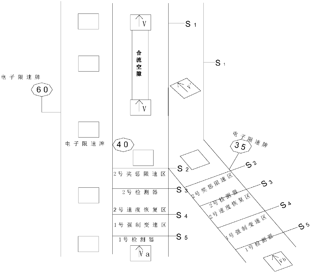
[0016] Specific implementation mode one: as figure 1 As shown, a traffic control method for weaving vehicles in a road merging area is realized through the following steps:

[0017] Step 1. Investigate the merging speed of vehicles on the main road in the road merging area, the merging speed of vehicles on the auxiliary road, the maximum speed limit of the main road, the maximum speed limit of the auxiliary road, and road geometric conditions;

[0018] Step 2, determining the positions of the detector, the forced speed change area, the speed recovery area, the reward and punishment speed limit area, and the variable speed limit device;

[0019] Step 3: According to the positions of the detector, the forced speed change area, the speed recovery area, the reward and punishment speed limit area, and the variable speed limit device determined in step 2, determine the traffic control rules for the weaving vehicles in the merge area.

specific Embodiment approach 2

[0020] Embodiment 2: The difference between this embodiment and Embodiment 1 is that the specific process of the step 1 is: the merging speed of the vehicles on the main road and the merging of vehicles on the auxiliary roads in the road merging area to be controlled before and after peak hours The speed is collected for 3 hours, and the width of the road in the merge area and the length of the acceleration lane in the merge area are measured.

[0021] Other steps and parameters are the same as those in Embodiment 1.

specific Embodiment approach 3

[0022] Specific embodiment three: the difference between this embodiment and specific embodiment one or two is that: in the step two, the specific steps for determining the position of the detector, the forced speed change area, the speed recovery area, the reward and punishment speed limit area, and the variable speed limit device are as follows: The process is:

[0023] set S 1 is the location of the merging area; the forward direction of the vehicle is taken as the positive direction, and the end position of the reward and punishment speed limit area of ​​the main road and auxiliary road is S 2 , and at S 2 Position setting variable speed limiting device;

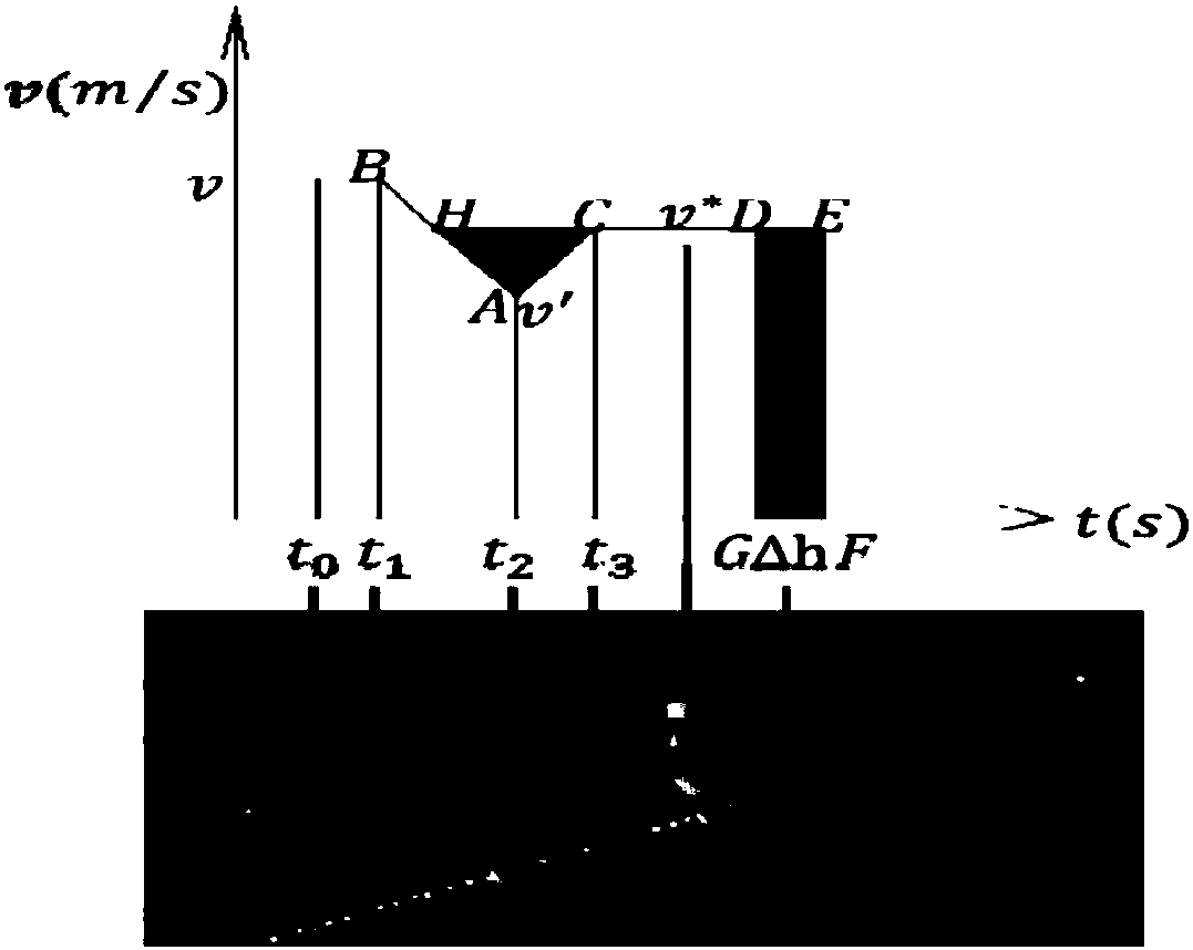
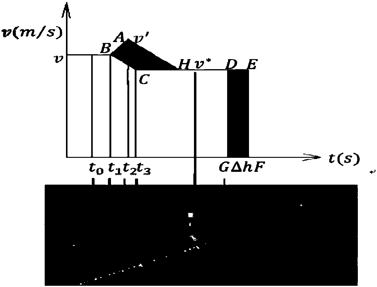
[0024] If the vehicle is leaving the variable speed limiter position S 2 To the merge position S 1 Unauthorized speed change during the period will make the merge impossible to complete as required, so S 1 S 2 In order for the vehicle to be adjusted by deceleration acceleration or acceleration deceleration model, t...


PUM


Abstract

The invention relates to a traffic control method of weaving vehicles in a road merging area, and aims at solving the problem that vehicles arriving at the merging area are slowed down to watch and then pass, resulting in traffic delay and heavy traffic in zipper-like traffic laws implemented on the merging area in peak hours. The method comprises the following steps: 1, investing the merging speed of vehicles in main pads in the road merging area, the merging speed of the vehicles in side roads, the maximum speed limitation of the main road, the maximum speed limitation of the side roads, andgeometric conditions of the roads; 2, determining the locations of a detector, a forced speed change area, a speed recovery area, a rewarding and punishing speed limitation area and a variable speedlimiting device; 3, determining the traffic control rules of the weaving vehicles in the merging area based on the positions, determined in step 2, of the detector, the forced speed change area, the speed recovery area, the rewarding and punishing speed limitation area and the variable speed limiting device. The method is applicable to the technical field of traffic information engineering and control.

Description

technical field [0001] The invention relates to a traffic control method for weaving vehicles in a road merge area, and belongs to the technical field of traffic information engineering and control. Background technique [0002] In the urban traffic system, the traffic capacity of the road merging area is one of the important factors affecting the road traffic capacity. However, in the existing urban road system, there are a large number of diverging and merging intersections without corresponding traffic management and control facilities. This leads to an increase in the number of vehicles that weave and change lanes in the diverging and merging areas during the morning and evening rush hours, making the diverging and merging areas a "bottleneck" and causing traffic congestion. With the accumulation of time, local congestion in the converging area of ​​urban roads will spread to the entire urban road traffic network, eventually leading to a decline in the overall traffic ca...

Claims


Application Information

Patent Timeline
IPC IPC(8): G08G1/07E01C1/02
CPCE01C1/02G08G1/075
Inventor 章锡俏杨龙海王刚王宇隋孟霖宋浩然
Owner HARBIN INST OF TECH
Why Eureka
Try Eureka