Electrolytic capacitor sealing machine

An electrolytic capacitor and sealing machine technology, applied in capacitors, capacitor manufacturing, circuits, etc., can solve problems such as poor sealing and unstable operation of capacitors, and achieve the effects of reducing poor product sealing, improving product quality, and convenient operation.

Inactive Publication Date: 2018-07-24
NANTONG HICON ELECTRONICS
View PDF3 Cites 3 Cited by
  • Summary
  • Abstract
  • Description
  • Claims
  • Application Information

AI Technical Summary

Problems solved by technology

[0006] In view of this, the main purpose of the present invention is to provide a capacitor that can solve the problem of poor sealing and unstable operation when the capacitor is sealed at the waist, can reduce the phenomenon of poor sealing of products, improve product quality, have a high degree of automation, save manpower, and improve production. Efficient Electrolytic Capacitor Sealing Machine

Method used


Image

  • Electrolytic capacitor sealing machine

Examples


Embodiment 1

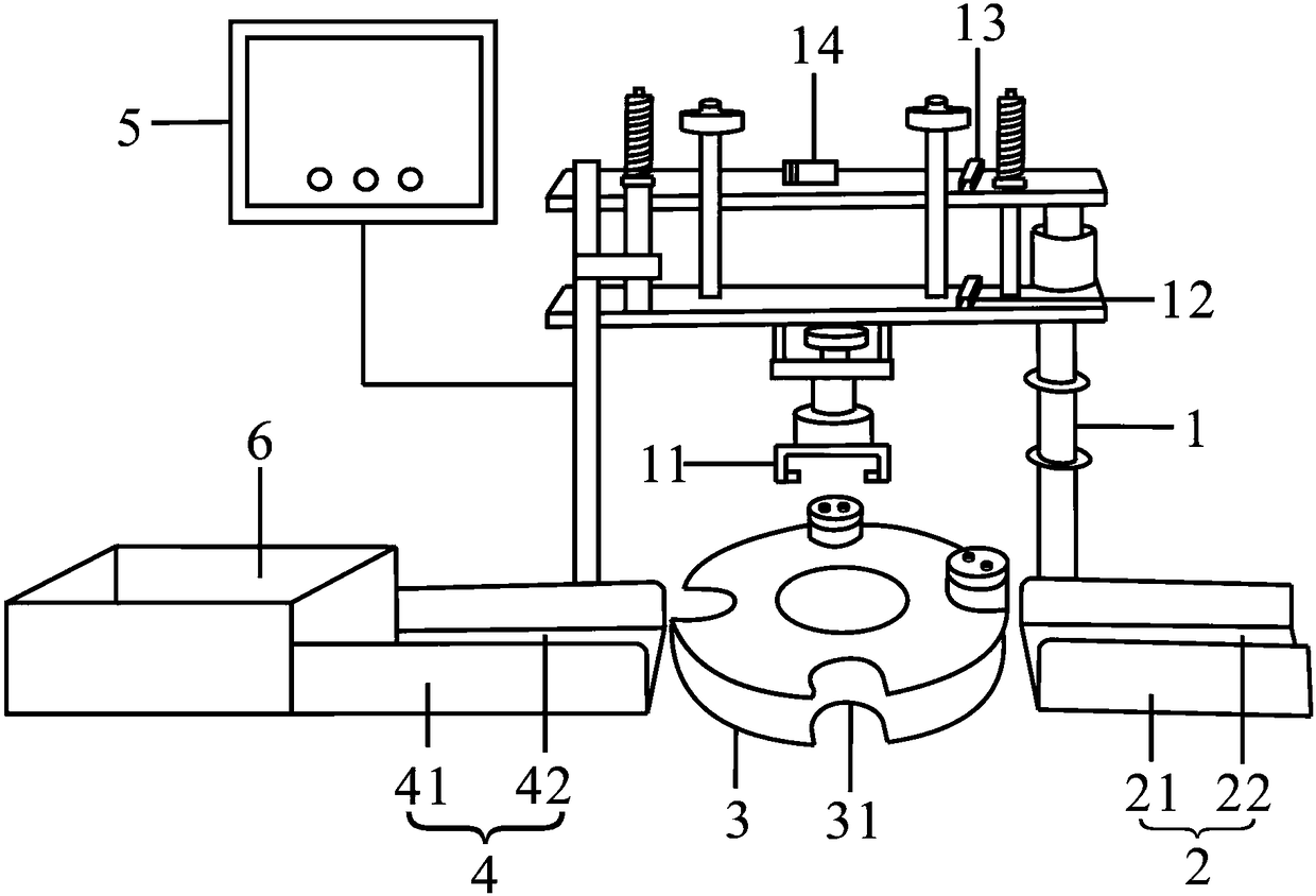
[0024] see figure 1 ,Such as figure 1 As shown, the present invention discloses an electrolytic capacitor sealing machine, which is used to automatically seal electrolytic capacitors to be sealed, including a frame 1, a conveying mechanism 2, a rotating disk 3, an output mechanism 4, a control unit 5 and an electrolytic capacitor collecting table 6. The frame 1 is provided with a sealing fixture 11, the sealing fixture 11 is used to clamp and seal the electrolytic capacitor, the rotating disk 3 is arranged directly under the sealing fixture 11, and the rotating The disc 3 is used to rotate the electrolytic capacitor on the conveying mechanism 2 to directly below the sealing fixture 11, the conveying mechanism 2 and the output mechanism 4 are respectively arranged on both sides of the rotating disc 3, the control unit 5 and the The rack 1 is electrically connected. The control unit 5 is a PLC controller.

[0025] The frame 1 is also provided with a pneumatic cylinder 12, a h...

Embodiment 2

[0030] The invention discloses an electrolytic capacitor sealing machine, which is used for automatic sealing of electrolytic capacitors to be sealed, comprising a frame 1, a conveying mechanism 2, a rotating disk 3, an output mechanism 4, a control unit 5 and an electrolytic capacitor collecting table 6. The frame 1 is provided with a sealing jig 11, the sealing jig 11 is used to clamp and seal the electrolytic capacitor, the rotating disc 3 is arranged directly below the sealing jig 11, and the rotating disc 3 is used for When the electrolytic capacitor on the conveying mechanism 2 is rotated to directly below the sealing fixture 11, the conveying mechanism 2 and the output mechanism 4 are respectively arranged on both sides of the rotating disk 3, the conveying mechanism 2, the The rotating disc 3 and the output mechanism 4 are on the same straight line.

[0031] The control unit 5 is electrically connected to the rack 1 . The control unit 5 is a PLC controller. The PLC c...


PUM


Abstract

The invention discloses an electrolytic capacitor sealing machine, which is used for automatically sealing the electrolytic capacitor to be sealed. The electrolytic capacitor sealing machine comprisesa rack, a conveying mechanism, a rotating disc, an output mechanism, a control unit, and an electrolytic capacitor collecting table. The rack is provided with a sealing clip, used for tightly clipping and sealing the electrolytic capacitor. The rotating disc is rotatably disposed right below the sealing clip, and is used for rotating the electrolytic capacitor on the conveying mechanism to a place right below the sealing clip. The conveying mechanism and the output mechanism are respectively disposed at two sides of the rotating disc, and the control unit is electrically connected to the rack. The invention is advantageous in that the problem of a capacitor that sealing is not good and running is not stable during the time when the capacitor is sealed can be resolved; the cover plate andthe housing can be stably and steadily sealed in an accurate, convenient, and rapid manner; the phenomena of not-good sealing can be reduced, product quality can be improved and production cost can bedeclined.

Description

technical field [0001] The invention relates to the technical field of electrolytic capacitor production equipment, in particular to an electrolytic capacitor sealing machine. Background technique [0002] Electrolytic capacitors are irreplaceable basic components in various electronic products. They mainly perform functions such as filtering, energy conversion, and power transmission. They have the following advantages: (1) The capacitance per unit volume is very large; (2) The rated capacity can be made (3) The price has an advantage over other types. Therefore, it is widely used in power supplies, motherboards, electronic energy-saving lamps, communication machines, electronic complete machines, instruments and meters, etc. [0003] An electrolytic capacitor mainly includes a core package, a case and a cover plate. In the production process of electrolytic capacitors, after the core package is put into the casing, both ends of the casing need to be waisted and sealed. ...

Claims


Application Information

Patent Timeline
Patent Type & Authority Applications(China)
IPC IPC(8): H01G13/00
Inventor 朱军毛建陈金建张诚志
Owner NANTONG HICON ELECTRONICS
Why Eureka
Try Eureka