
Light-emitting keyboard

A technology of luminous keyboards and keycaps, which is applied in legends, electrical components, electric switches, etc., can solve the problems of reduced production capacity, increased product cost, and poor environmental protection, and achieves the goal of reducing product cost, reducing component composition, and improving product yield. Effect

Pending Publication Date: 2018-07-24
深圳新纳光电科技有限公司
View PDF8 Cites 0 Cited by
  • Summary
  • Abstract
  • Description
  • Claims
  • Application Information

AI Technical Summary

Problems solved by technology

With the rapid development of science and technology, the thickness of the keyboard is also becoming thinner and thinner with people's requirements. In the existing production of the keyboard structure, in order to make the thickness of the keyboard thinner, generally by using the thinnest possible keycap , rubber elastic body, but in the case of ensuring the normal use of the keyboard, the thickness of the keyboard with this structure can no longer be made thinner, and it still cannot meet people's requirements for thinner keyboards
At the same time, the keycaps of the existing luminous keyboards all need to be treated with a spraying process, so that the area where the key logo is displayed on the keycap can transmit light, and the rest of the areas are all shaded. This will undoubtedly increase the manufacturing process of the luminous keyboard, reduce production capacity, and increase The cost of the product, and the process of spraying shading pigments will often pollute the environment, and the environmental protection is poor

Method used


Image

  • Light-emitting keyboard
  • Light-emitting keyboard
  • Light-emitting keyboard

Examples


Embodiment Construction

[0031] In order to further illustrate the technical means adopted by the present invention and its effects, the following describes in detail in conjunction with preferred embodiments of the present invention and accompanying drawings.

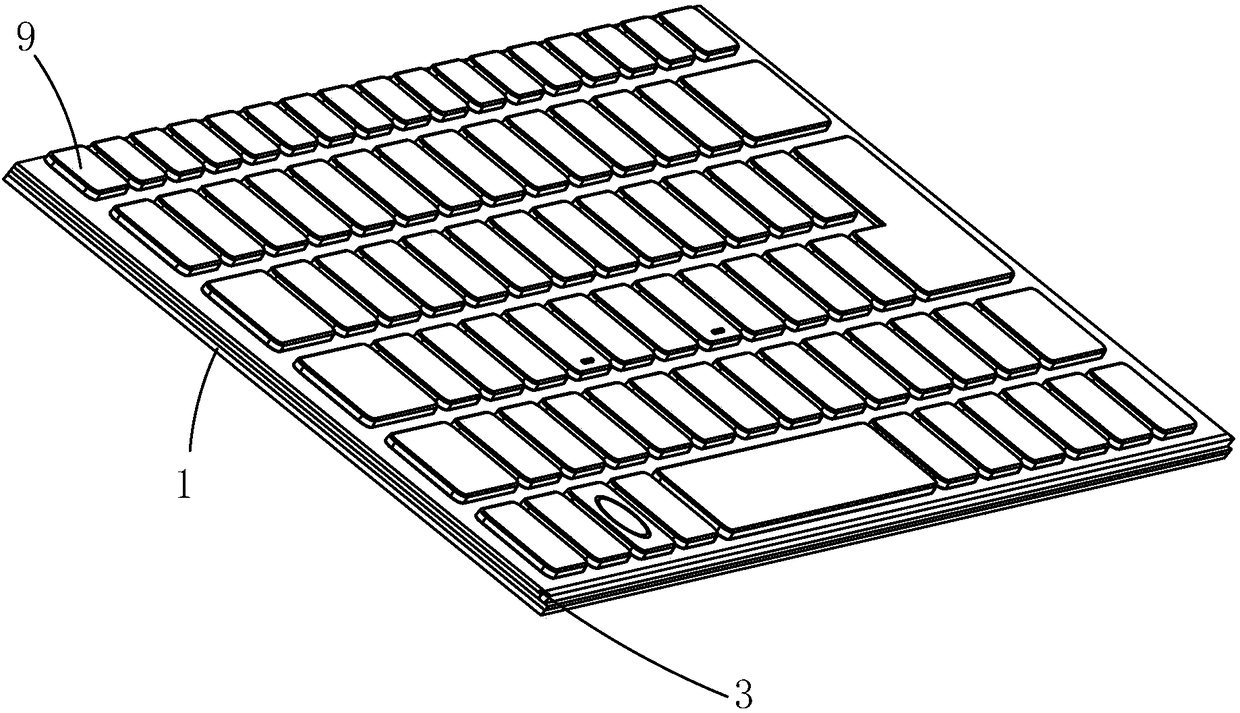
[0032] see Figure 3 to Figure 7 , the first embodiment of the luminous keyboard of the present invention comprises a backboard 1, a thin film circuit board 3 arranged above the backboard 1, an elastic body 5 arranged above the thin film circuit board 3, and an elastic body 5 arranged above the thin film circuit board. The scissor feet 7 installed on the backboard 1 above the board 3 and the elastic body 5 , and the keycap 9 installed above the scissor feet 7 . Described film circuit board 3 comprises a first circuit board 32, a second circuit board 34 opposite to the first circuit board 32, a middle partition 36 arranged between the first circuit board 32 and the second circuit board 34, and Corresponding to the light source 38 provided on t...


PUM


Abstract

The invention provides a light-emitting keyboard. A thin film circuit board of the light-emitting keyboard comprises a first circuit board, a second circuit board, an intermediate partition plate anda light source, wherein the second circuit board is arranged opposite to the first circuit board, the intermediate partition plate is arranged between the first circuit board and the second circuit board, and the light source is arranged corresponding to the second circuit board. The second circuit board is made of a light guide plate, and light emitted from the light source is guided through thesecond circuit board and then irradiates towards a key cap; and compared with the light-emitting keyboard of the prior art, the light-emitting keyboard is smaller in thickness, the light and thin design of the light-emitting keyboard is facilitated, the thinning requirement of people on the light-emitting keyboard can be met, moreover, the component number of the light-emitting keyboard is effectively reduced, the assembly process is reduced, the product yield is improved, and the product cost is reduced.

Description

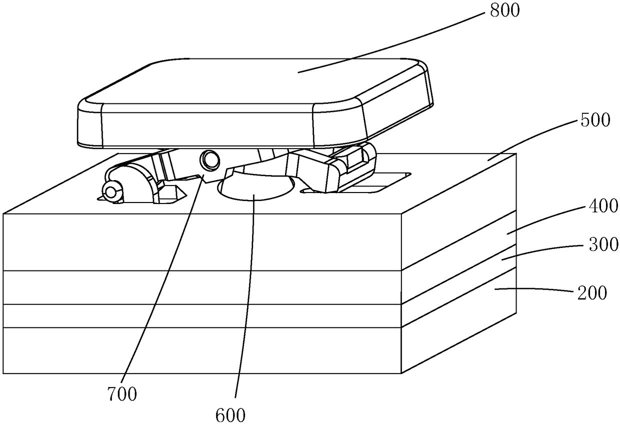
technical field [0001] The invention relates to the technical field of computer accessories, in particular to a luminous keyboard. Background technique [0002] As a common input device, the keyboard is widely used in the input of computers and various electronic products. With the widespread use of electronic products, the keyboard occupies a very important position in the entire system as a means of man-machine communication. [0003] Such as figure 1 As shown, an existing light-emitting keyboard includes a backboard 200, a light-emitting board 300, a light guide plate 400, a thin film circuit board 500, an elastic body 600, scissor feet 700, and a keycap 800, and the keycap 800 passes through the scissor feet 700. installed on the backplane 200. Such as figure 2 as shown, figure 1 The film circuit board 500 of the luminous keyboard comprises a first circuit board 510, a second circuit board 530 opposite to the first circuit board 510, and a middle partition 520 betw...

Claims


Application Information

Patent Timeline
Patent Type & Authority Applications(China)
IPC IPC(8): H01H13/83H01H13/02
CPCH01H13/023H01H13/83H01H2219/054H01H2227/036
Inventor 蓝利芹
Owner 深圳新纳光电科技有限公司
Learn More