Wind power-photothermal joint power generation system and operation method thereof

A combined power generation and electronic system technology, applied in wind power generation, solar heating systems, electrical components, etc., can solve the problems of short battery life, imperfect adjustment measures, and low energy storage efficiency

Active Publication Date: 2018-07-24
HOHAI UNIV
View PDF5 Cites 20 Cited by
  • Summary
  • Abstract
  • Description
  • Claims
  • Application Information

AI Technical Summary

Problems solved by technology

With a photovoltaic power station as a regulating power source, the peak energy storage efficiency of the battery is only about 70%, and the characteristics of wind power and photovoltaic power generation will cause the battery in the wind and solar (volt) storage (battery) system to be in a state of power loss for a long time, and the battery life is short. high cost
It is an ideal measure to use a pumped storage power station as a regulation power source, but the pumped storage power station is severely restricted by the region
In addition, if the compressed air is directly used for energy storage, the energy loss is as high as about 50%, and the energy storage efficiency is low.
In summary, although the existing adjustment measures mentioned above are feasible, they are not perfect.

Method used


Image

  • Wind power-photothermal joint power generation system and operation method thereof
  • Wind power-photothermal joint power generation system and operation method thereof
  • Wind power-photothermal joint power generation system and operation method thereof

Examples


Embodiment Construction

[0061] The present invention will be further described below in conjunction with the accompanying drawings. The following examples are only used to more clearly illustrate the technical solutions of the present invention, and cannot be used to limit the protection scope of the present invention.

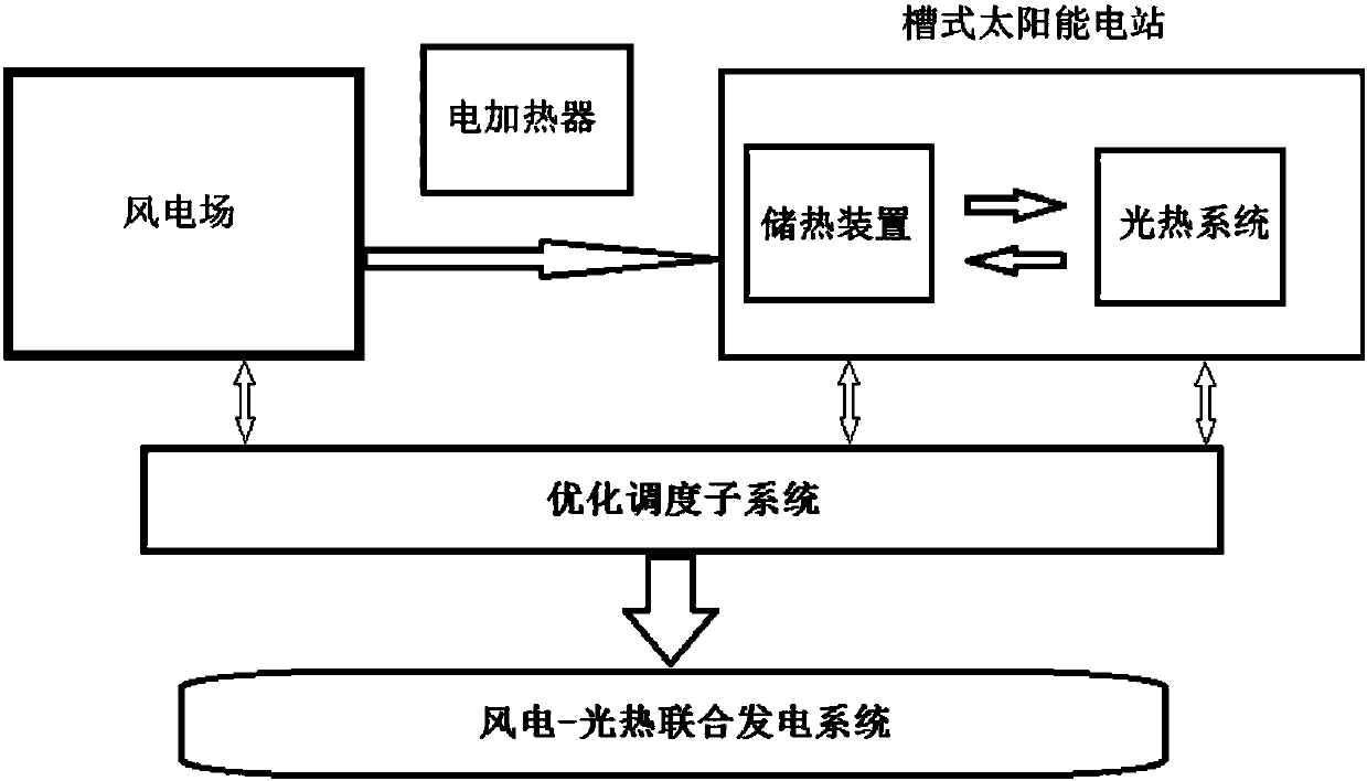
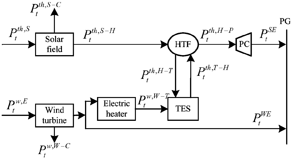
[0062] The structure of wind power-photothermal combined power generation system is as follows: figure 1 As shown, the combination of wind farm and trough solar thermal power station is taken as an example, and other solar thermal power stations have similar structures. The combined power generation system is mainly composed of wind electronic system, photothermal subsystem, electric heating subsystem and optimal dispatching subsystem. The wind electronic system is connected with the photothermal subsystem through the electric heating subsystem. The photothermal subsystem is composed of a solar concentrating heat collecting subsystem, a heat storage subsystem, and a power cycle (PC...


PUM


Abstract

The invention discloses a wind power-photothermal joint power generation system. The power generation system is characterized by comprising a wind power sub system, a photothermal sub system, an electric heating sub system and an optimization dispatching sub system; the wind power sub system is connected with the photothermal sub system through the electric heating sub system; and the optimizationdispatching sub system is connected with the wind power sub system and the photothermal sub system separately. The power generation system has the advantages as follows: 1) wind power and CSP are totally used as a node of a power grid for suppressing wind power fluctuation before wind power is connected to the power grid, thereby enabling the joint system to dispatch like a conventional power generation system, and reducing impact of wind power to the power grid; 2) by adding an electric heating apparatus to the system, the wind resource utilization rate is improved; and 3) by taking the maximum of the operational benefit of the wind power-CSP joint power generation system as the target in the optimization dispatching sub system, wind curtailment is lowered effectively, thereby achievingrelatively high schedulability, safety and economic efficiency.

Description

technical field [0001] The invention relates to a wind power-photothermal combined power generation system and an operation method thereof, belonging to the technical field of power generation. Background technique [0002] With the continuous consumption of global fossil fuels and the deterioration of the ecological environment, the use of renewable energy to generate electricity has received more and more attention. Wind power is currently the most mature and lowest-cost form of renewable energy power generation besides hydropower. Wind power will provide 9% of global electricity by 2030; this figure will reach 12% by 2050. By the end of 2014, the installed capacity of grid-connected wind power in my country had reached 95.81 million kilowatts. However, due to the randomness and intermittency of wind resources, the controllability and dispatchability of wind power are poor, and the direct connection of a large proportion of wind power to the grid will bring potential ris...

Claims


Application Information

Patent Timeline
Patent Type & Authority Applications(China)
IPC IPC(8): H02J3/38H02J3/28H02J3/46F24S20/20F24S20/40F24S60/00
CPCH02J3/386H02J3/28H02J3/46H02J2203/20Y02E10/76Y02E70/30
Inventor 郭苏杨勇许昌李荣
Owner HOHAI UNIV
Why Eureka
Try Eureka