A laser engraving device

A technology of laser engraving and polishing wheel, used in laser welding equipment, metal processing equipment, welding equipment and other directions, can solve problems such as single function, and achieve the effect of convenient operation and simple structure

Active Publication Date: 2019-01-11
HAIXI (FUJIAN) INST CHINA ACAD OF MASCH SCI&TECH GRP
View PDF4 Cites 0 Cited by
  • Summary
  • Abstract
  • Description
  • Claims
  • Application Information

AI Technical Summary

Problems solved by technology

The physical denaturation of the processed material is instantly melted and vaporized under laser irradiation to achieve the purpose of processing. Traditional laser engraving facilities usually have a single function, only a single local laser engraving function. Usually, the processed material needs to be polished before laser engraving. To make the material surface in a smooth state, therefore, it is urgent to design a laser engraving and polishing integrated equipment

Method used


Image

  • A laser engraving device
  • A laser engraving device

Examples


Embodiment Construction

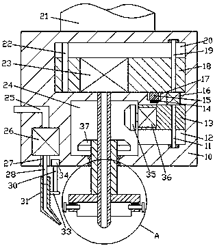
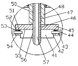
[0013] Combine below Figure 1-2 The present invention will be described in detail.

[0014] refer to Figure 1-2 , a laser engraving device according to an embodiment of the present invention, including a processing body 10 fixedly installed on the lower side of the adjusting arm 21, a transmission cavity 24 is provided in the inner wall of the processing body 10, and the top of the transmission cavity 24 The processing main body 10 is provided with an adjustment cavity 20, and an adjustment bracket 18 is installed in the adjustment cavity 20 for sliding fit, and a sliding cavity 12 is connected to the inner wall of the right side of the transmission cavity 24, and a sliding cavity 12 is installed in the sliding cavity 12 for sliding fit. There is a sliding seat 13, and a first motor 16 is fixed between the sliding chamber 12 and the regulating chamber 20, and the top end of the first motor 16 is dynamically connected to an upper threaded rod 19, and the upper threaded rod 1...


PUM


Abstract

The invention discloses a laser engraving device. The laser engraving device comprises a machining main body which his fixedly installed at the lower side of a regulating arm; the inner wall body of the machining main body is internally provided with a passing and receiving chamber; a part, positioned at the top of the passing and receiving chamber, of the machining main body is internally provided with a regulating chamber; a regulating frame is installed inside the regulating chamber in a sliding fit manner; the inner wall of the right side of the passing and receiving chamber is provided with a sliding chamber which communicates with the passing and receiving chamber; a sliding seat is installed inside the sliding chamber in a sliding fit manner; a first motor is fixedly arranged between the sliding chamber and the regulating chamber; the top end of the first motor is in power matched connection with an upper threaded rod; the upper threaded rod is connected with the regulating frame in a thread fit manner; the tail end of the top of the upper threaded rod is connected with the internal top wall of the regulating chamber in a running fit manner; the bottom end of the first motoris in power matched connection with a lower threaded rod; the lower threaded rod is connected with the sliding seat in a thread fit manner; and the tail end of the bottom of the lower threaded rod isconnected with the internal bottom wall of the sliding chamber in a running fit manner.

Description

technical field [0001] The invention relates to the technical field of numerical control processing, in particular to a laser engraving device. Background technique [0002] Laser engraving is based on numerical control technology, and laser is the processing medium. The physical denaturation of the processed material is instantly melted and vaporized under laser irradiation to achieve the purpose of processing. Traditional laser engraving facilities usually have a single function, only a single local laser engraving function. Usually, the processed material needs to be polished before laser engraving. To make the material surface in a smooth state, therefore, it is urgent to design a laser engraving and polishing integrated equipment. Contents of the invention [0003] The object of the present invention is to provide a laser engraving device for overcoming the above-mentioned defects in the prior art. [0004] A laser engraving device according to the present invention...

Claims


Application Information

Patent Timeline
Patent Type & Authority Patents(China)
IPC IPC(8): B23K26/362B23K26/70
CPCB23K26/361B23K26/702
Inventor 何龙飞
Owner HAIXI (FUJIAN) INST CHINA ACAD OF MASCH SCI&TECH GRP
Why Eureka
Try Eureka