Vibrating device and vibrating method of cast-in-place pile concrete

A vibrating device and cast-in-place pile technology, which is applied in construction and basic structure engineering, can solve the problems of concrete vibrating not compacted, affecting the life of the structure, and reducing the bearing capacity, so as to prevent pipe plugging, avoid quality accidents, and ensure pouring Effect

Active Publication Date: 2018-07-27
MCC COMM CONSTR GRP CO LTD
View PDF3 Cites 2 Cited by
  • Summary
  • Abstract
  • Description
  • Claims
  • Application Information

AI Technical Summary

Problems solved by technology

[0003] If the concrete is not dense, the section of the pile will be weakened and the bearing capacity will decrease.
Moreover, because the concrete is not dense, there are tiny holes and cracks, and the external moisture, salt and gas can easily invade the interior, corrode the steel bars, cause premature damage to the structure, and affect the life of the structure.
However, the current plug-in concrete vibrating device cannot effectively vibrate the concrete of the bored pile, so it is necessary to further improve the current concrete vibrating device to avoid the danger of uncompacted concrete vibration

Method used


Image

  • Vibrating device and vibrating method of cast-in-place pile concrete
  • Vibrating device and vibrating method of cast-in-place pile concrete
  • Vibrating device and vibrating method of cast-in-place pile concrete

Examples


Embodiment Construction

[0025] Embodiments of the concrete vibrating device for cast-in-situ piles and the vibrating method thereof according to the present invention will be described below with reference to the accompanying drawings. Those skilled in the art would recognize that the described embodiments can be modified in various ways or combinations thereof without departing from the spirit and scope of the invention. Accordingly, the drawings and description are illustrative in nature and not intended to limit the scope of the claims. Also, in this specification, the drawings are not drawn to scale, and like reference numerals denote like parts.

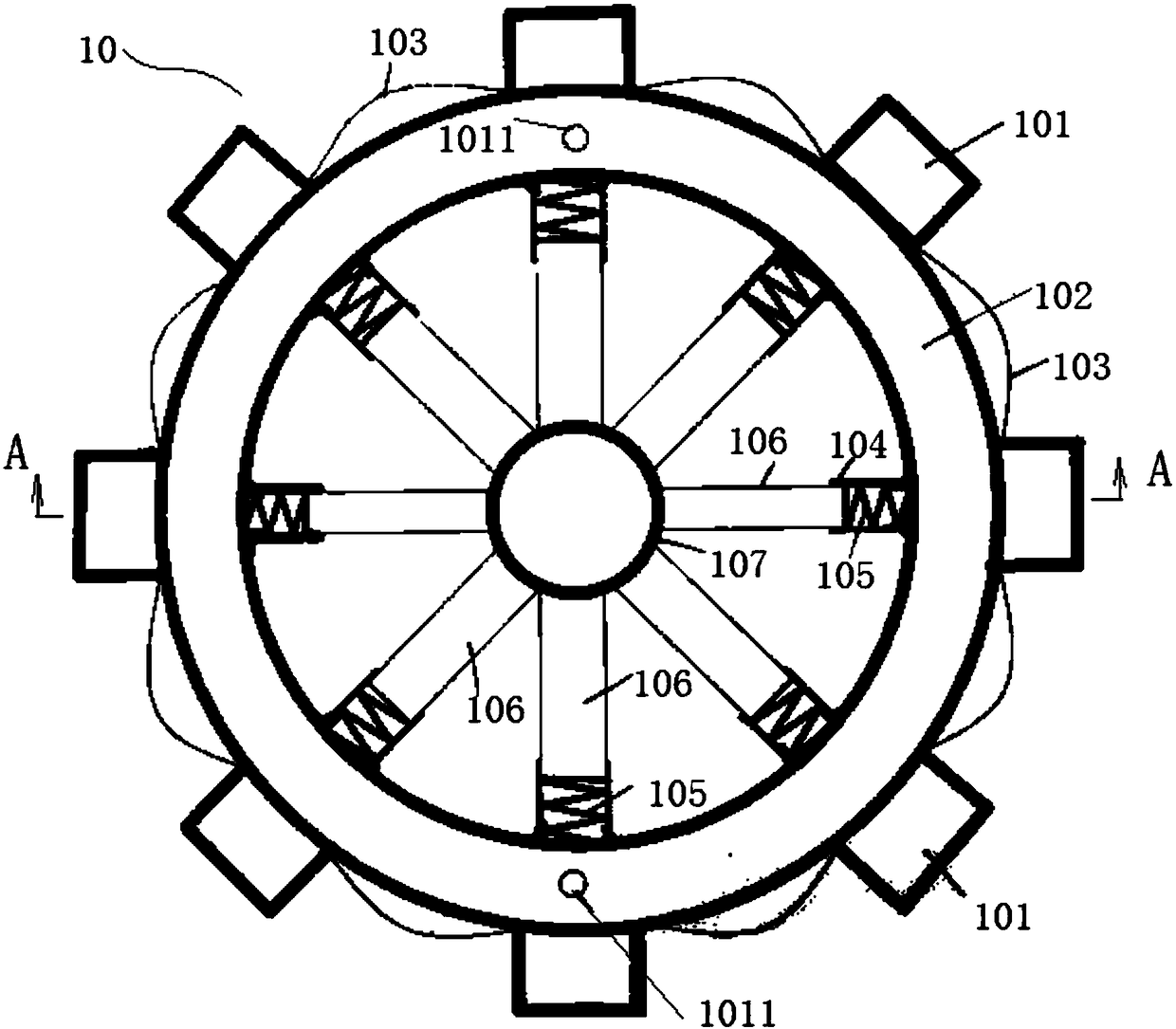
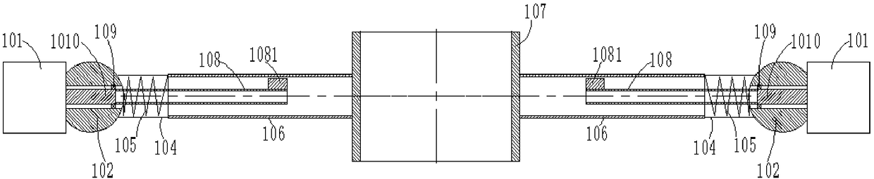
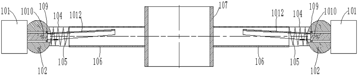
[0026] A vibrating device for cast-in-situ pile concrete, such as figure 1 , figure 2 As shown, it includes a motor 101 , a vibration ring 102 , a cable 103 , a vibration sleeve 106 and a positioning cylinder 107 . The vibrating ring 102 is annular, and one or more motors 101 are arranged outside the outer circumference of the vibrating ring 102, a...


PUM


Abstract

The invention relates to a vibrating device and a vibrating method of cast-in-place pile concrete. The vibrating device comprises a vibrating ring, one or more motors, a positioning barrel, and one ormore vibrating sleeves, wherein the motors are arranged at the periphery of the vibrating ring in a circumferential direction; rotating shafts of the motors inwards penetrate through the vibrating ring in a radial direction of the vibrating ring; the positioning barrel is a hollow tube body and coaxially arranged in the center of the vibrating ring; the vibrating sleeves are connected between thepositioning barrel and the vibrating ring and internally provided with vibrating shafts; one end of each vibrating shaft is connected with each rotating shaft of the motor; an eccentric block is arranged at the other end of each vibrating shaft; and when the vibrating shafts rotate, the eccentric block continuously collide peripheral internal walls of the vibrating sleeves to further drive the vibrating ring to generate high-frequency vibration. A compaction pile foundation is filled with the concrete vibrated by the vibrating device of the cast-in-place pile concrete, and the grip of the concrete and a steel reinforcement cage is better. The pile body concrete is bonded with soil around the concrete more securely. A conduit vibrates by the action of the vibrating device; the flow of theconcrete in the conduit is accelerated; and a blocking phenomenon due to poor placeability of the concrete is avoided.

Description

technical field [0001] The invention relates to the field of building construction, in particular to a concrete vibrating device for a cast-in-place pile and a vibrating method thereof. Background technique [0002] At present, concrete is an overall dense engineering composite material formed by combining aggregates with cementitious materials (cement). It has been widely used in basic construction fields such as construction engineering, bridge engineering, and traffic engineering. Under normal circumstances, the bored pile does not use the mechanical vibration filling method, that is, the dense concrete is used, but the concrete mixture will be mixed with a certain amount of air during the stirring, transportation, and pouring process, and the concrete will be mixed with the admixture after adding the admixture. Bubbles increase, and the internal porosity increases after the concrete solidifies and hardens. After coring the concrete of the bored pile, it is found that th...

Claims


Application Information

Patent Timeline
Patent Type & Authority Applications(China)
IPC IPC(8): E02D15/04
CPCE02D15/04
Inventor 刘思谋
Owner MCC COMM CONSTR GRP CO LTD
Why Eureka
Try Eureka