Illumination module

A lighting module and floodlighting technology, which is applied to lighting devices, lighting and heating equipment, components of lighting devices, etc., can solve problems such as product yield decline, miniaturization, light and thin integration difficulties, and increased production costs.

Active Publication Date: 2018-07-27
SHENZHEN ORBBEC CO LTD
View PDF5 Cites 20 Cited by
  • Summary
  • Abstract
  • Description
  • Claims
  • Application Information

AI Technical Summary

Problems solved by technology

The trend of miniaturization and thinning of smart devices makes it extremely difficult to integrate so many devices
On the one hand, more devices will bring higher power consumption, which will reduce the battery lif

Method used


Image

  • Illumination module
  • Illumination module
  • Illumination module

Examples


Embodiment Construction

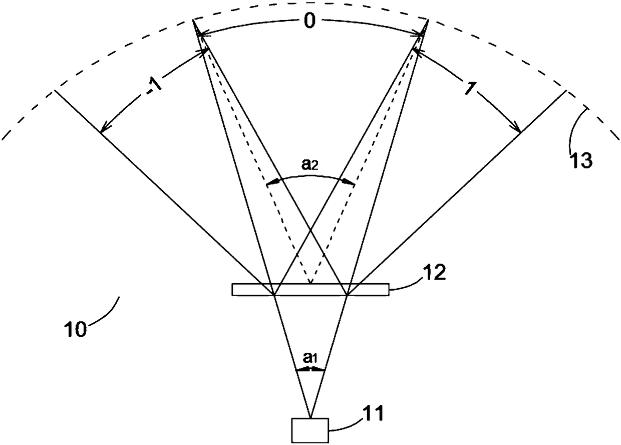
[0030] figure 1 It is a schematic diagram of a flood lighting module according to an embodiment of the present invention. The module 10 includes a light source 11 and a diffractive optical element (DOE) 12. The light source 11 can be a light source such as an LED or a laser for emitting infrared, ultraviolet, visible light and other light beams. The light source 11 emits a light beam and forms an incident light beam on the incident surface of the DOE12. After receiving the incident light beam, the DOE12 diffracts the incident light beam and diffuses it into a wider space 13 to realize flood lighting. In one embodiment, the DOE12 plays the role of beam splitting. The role is to copy and expand a single incident beam into multiple outgoing beams without changing the basic properties, where the basic properties include beam size, polarization direction, phase, divergence angle, etc. Such as figure 1 As shown, the light beam emitted by the light source 11 is diffracted by the DO...


PUM


Abstract

The invention provides an illumination module which comprises a light source, a lens, a diffractive optical element and a processor, wherein the light source is used for transmitting light beams; thelens is used for diverging or converging the light beams; the diffractive optical element is used for duplicating and spreading the light beams to an illuminated space; and a processor is connected with and used for controlling one or more of the light source, the lens and the diffractive optical element, thereby achieving floodlight illumination or structured light illumination. According to theillumination module, one or more of the light source, the lens and the diffractive optical element can be regulated through the processor, thereby meeting the floodlight illumination or structured light illumination conditions, and achieving floodlight illumination or structured light illumination; the floodlight illumination function and the structured light projection function are integrated into one module and can be switched over as required at any time, thereby achieving floodlight illumination or structured light illumination; and furthermore, the illumination module has the characteristics of being small in size and low in power consumption, and is beneficial to the integration into intelligent equipment.

Description

technical field [0001] The invention relates to the field of semiconductor lighting, in particular to a lighting module. Background technique [0002] Visual information is gradually becoming an important way for smart devices to obtain information and perceive the world. With the increasing functions of smart devices and the diversification of application scenarios, the demands based on visual information are becoming more and more extensive. For example, functional requirements such as unlocking and payment based on face recognition, gesture and action interaction based on human body information, and these functions also need to have high reliability in different scenarios and under different environmental lighting conditions. In traditional equipment, it is difficult to use cameras to obtain color image information to meet these requirements. The acquisition of visual information based on active lighting, such as infrared images, can improve the reliability of visual info...

Claims


Application Information

Patent Timeline
IPC IPC(8): F21S2/00F21V5/04F21V5/00F21V23/00F21V19/00
CPCF21S2/00F21V5/00F21V5/004F21V5/04F21V19/00F21V23/003
Inventor 许星
Owner SHENZHEN ORBBEC CO LTD
Why Eureka
Try Eureka