Heat dissipating and damping system of power amplifier

A technology of power amplifier and heat dissipation hole, which is applied in the direction of transducer shell/cabinet/stand, etc., can solve the problems of inconvenient installation of power amplifier, insufficient heat dissipation performance, poor shock resistance of reinforced power amplifier, etc., and achieves the effect of satisfying heat dissipation and prevention.

Inactive Publication Date: 2018-07-27
CHENGDU DIMAN TECH CO LTD
View PDF0 Cites 1 Cited by
  • Summary
  • Abstract
  • Description
  • Claims
  • Application Information

AI Technical Summary

Problems solved by technology

[0006] The purpose of the present invention is to overcome the deficiencies of the prior art, and the purpose is to provide a power amplifier heat dissipation and shockproof system to solve the problems of poor shock resistance, insufficient heat dissipation performance of the reinforced power amplifier, and inconvenient installation of the power amplifier in a reinforced box

Method used


Image

  • Heat dissipating and damping system of power amplifier
  • Heat dissipating and damping system of power amplifier
  • Heat dissipating and damping system of power amplifier

Examples


Embodiment 1

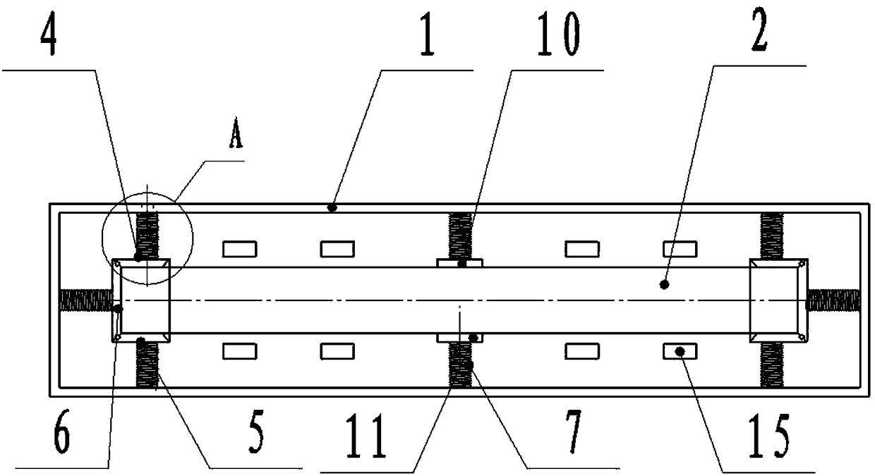
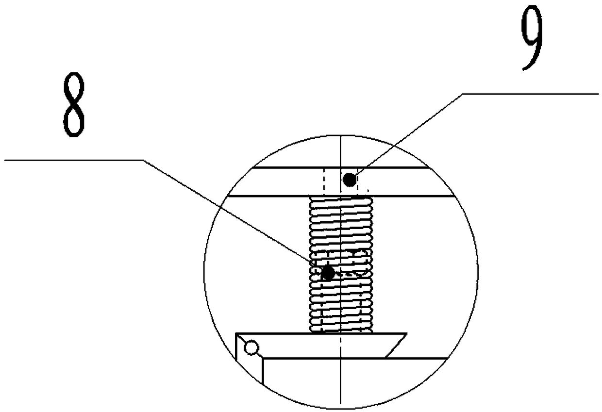
[0039] like Figure 1-3 As shown in the figure, a heat dissipation and anti-vibration system of a power amplifier of the present invention includes a power amplifier chassis 1 and a power amplifier body 2, the front end of the power amplifier chassis 1 is movably provided with a front baffle 3, and both sides of the power amplifier chassis 1 are provided with power amplifiers U Type clamping block, the power amplifier body 2 is clamped in two power amplifier U-shaped clamping blocks, and the power amplifier U-shaped clamping block includes an upper clamping plate 4, a lower clamping plate 5 and a side clamping plate 6. The upper clamping plate 4 and the side clamping plate 6 The upper end is hinged, the lower splint 5 is hinged with the lower end of the side splint 6, and the hinged connection can make the upper splint 4 and the lower splint 5 clamp the power amplifier body 2 firmly. The power amplifier chassis of the chassis 1 are connected by a shock-absorbing spring 7. The ...

Embodiment 2

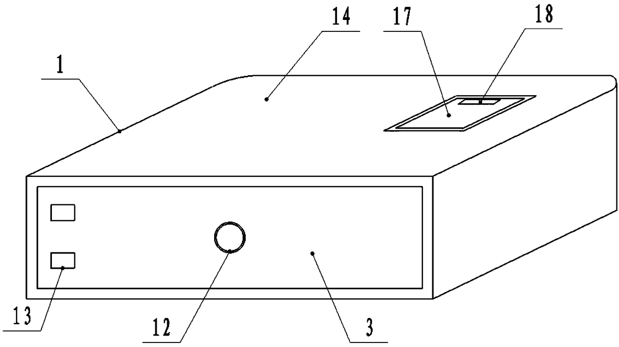
[0050] like Figure 1-8 As shown, a heat dissipation and shockproof system of a power amplifier of the present invention, on the basis of Embodiment 1, includes a power amplifier case 1 and a heat dissipation hole 16 arranged on the power amplifier case 1, and the power amplifier case 1 is provided with a movable The baffle 17 and the movable baffle 17 are slidably connected with the power amplifier case 1 and the sliding movable baffle 17 can make it block the cooling holes 16 and open the cooling holes 16 . Sliding movable baffle plate 17 controls the opening and closing of part of the heat dissipation holes 16, thereby adjusting the total area of ​​the heat dissipation holes 16 on the power amplifier cabinet 1. When the total area of ​​the heat dissipation holes 16 is large, it is beneficial to heat dissipation; When the area is small, it is good for dustproofing, and the shell can meet the needs of heat dissipation and dustproofing at the same time.

[0051] The connectio...


PUM


Abstract

The invention discloses a heat dissipating and damping system of a power amplifier. The system comprises a power amplifier chassis and a power amplifier main body, wherein a front baffle is arranged at a front end of the power amplifier chassis, power amplifier U-shaped clamp blocks are arranged on both sides in the power amplifier chassis, the power amplifier main body is clamped in the two poweramplifier U-shaped clamp blocks, each power amplifier U-shaped clamp block comprises an upper clamp plate, a lower clamp plate and a side clamp plate, the upper clamp plate is hinged with the upper end of the side clamp plate, the lower clamp plate is hinged with the lower end of the side clamp plate, the upper clamp plate, the lower clamp plate and the side clamp plate are connected with the power amplifier chassis through damping springs, connecting screws are arranged at the connection sites of the damping springs with the upper clamp plate, the lower clamp plate and the side clamp plate,and adjustment holes are formed in the power amplifier chassis corresponding to the connecting screws. Heat dissipating holes are formed in the power amplifier chassis, a movable baffle is arranged atthe heat dissipating holes on the power amplifier chassis, the movable baffle is slidably connected to the power amplifier chassis, and the sliding of the movable baffle can block the heat dissipating holes and open the heat dissipating holes.

Description

technical field [0001] The invention relates to the technical field of power amplifier equipment, in particular to a heat dissipation and shockproof system of a power amplifier. Background technique [0002] Power amplifier is referred to as power amplifier, commonly known as "amplifier". It is the most basic equipment in the audio system. Its task is to amplify the weak electrical signal from the signal source (from the mixer in the professional audio system) to drive the speaker to emit sound. . [0003] Power amplifiers can be said to be the largest family of all kinds of audio equipment. Its function is mainly to amplify the weaker signal input by the audio source equipment and generate enough current to drive the speaker to reproduce the sound. Due to the consideration of power, impedance, distortion, dynamics, as well as different use ranges and control and adjustment functions, different power amplifiers have different internal signal processing, circuit design and p...

Claims


Application Information

Patent Timeline
Patent Type & Authority Applications(China)
IPC IPC(8): H04R1/02
CPCH04R1/02
Inventor 罗勇
Owner CHENGDU DIMAN TECH CO LTD
Why Eureka
Try Eureka