Vehicle and power device thereof

A technology of power plant and installation position, applied in power plant, pneumatic power plant, electromechanical device, etc., can solve the problems of displacement, poor heat dissipation, and the parts to be lubricated cannot be lubricated continuously.

Active Publication Date: 2018-07-31
ZHENGZHOU YUTONG BUS CO LTD
View PDF28 Cites 5 Cited by
  • Summary
  • Abstract
  • Description
  • Claims
  • Application Information

AI Technical Summary

Problems solved by technology

However, the system still has the following problems at present: the device housing and the corresponding parts installed on the device housing need to be rotated and matched through bearings. 1. Bearings are installed on the rear transmission shaft bearing seat to realize the rotation fit between the device housing and the corresponding transmission shaft. The front and rear motor bearing seats need to be installed at the two ends of the first motor chamber and the planetary row chamber respectively. Bearings are installed on the bearing seat of the rear motor to realize the rotation fit between the rotor and the device housing. These positions where the bearings are installed need to be lubricated, and the position of the planetary row also needs to be lubricated. The current lubrication method is to fill these parts that need to be lubricated. Grease, the use of grease to lubricate these parts has the following defects. The grease may be displaced from the parts to be lubricated, resulting in the inability to continue to lubricate the parts to be lubricated, which may cause damage to bearings, gears, etc.; The generated impurities are taken away, the heat dissipation effect is not good, and the replacement of lubricating grease is also troublesome
And if the lubricating oil pump is simply provided to force these parts to be lubricated to be lubricated, in order to supply power to the lubricating oil pump, cable perforations must be set on the device housing, which involves new sealing problems, or leads to The structure of the whole device shell is more complex and prone to oil leakage

Method used


Image

  • Vehicle and power device thereof
  • Vehicle and power device thereof
  • Vehicle and power device thereof

Examples


Embodiment Construction

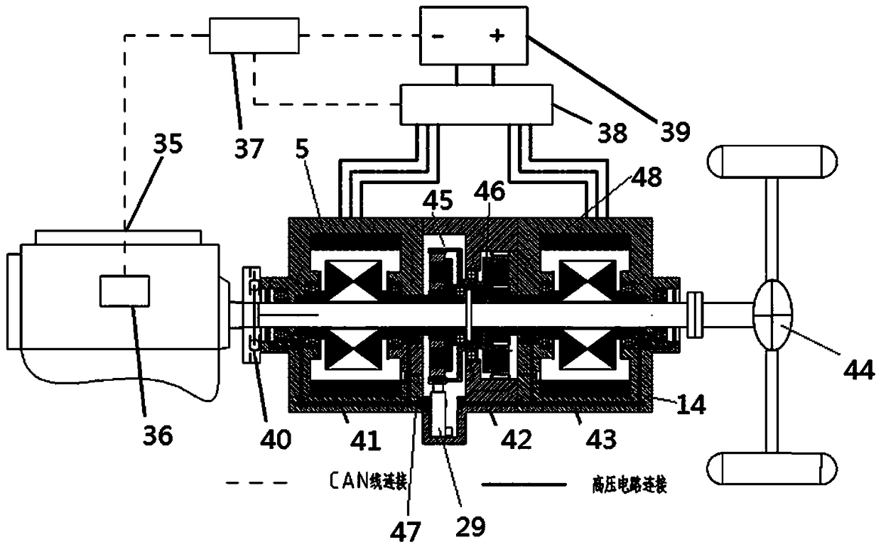
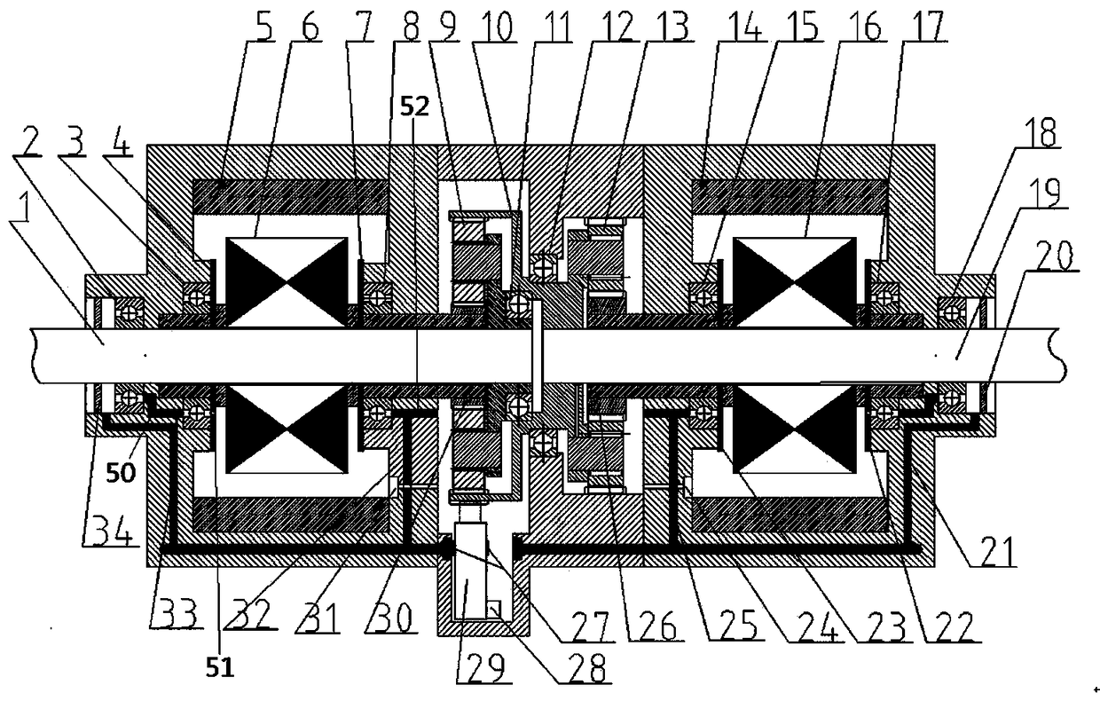
[0047] Examples of vehicles are Figure 1~3 Shown: including the vehicle frame and the power system arranged on the vehicle frame, the power system in this embodiment is a parallel hybrid system, the vehicle frame belongs to the prior art, and its structure will not be described in detail here. The series hybrid power system includes an engine 35 and a power unit, and the power unit includes a device housing, which is composed of a first motor housing 41, a planetary row housing 42, and a second motor housing 43 arranged in front and rear , wherein the rear end cover of the first motor housing and the front end cover of the second motor respectively form the first barrier 47 and the second barrier 48, and the two barriers separate the device housing into the first motor chamber, the planetary row chamber and the second motor chamber, the first motor chamber is provided with the first motor 5, the planetary row chamber is provided with the first planetary row 45 and the second ...


PUM


Abstract

The invention relates to a vehicle and a power device thereof. The power device comprises a device shell. The device shell is internally provided with a motor and a planet row, further provided with abearing mounting position used for mounting of a corresponding bearing, and internally provided with a lubricating oil pump; the lubricating oil pump is provided with a power input end in transmission connection with the planet row; the power device further comprises a lubricating oil channel connected with an oil outlet of the lubricating oil pump for guiding lubricating oil towards the planet row and / or the mounting position of the corresponding bearing; and the lubricating oil channel is constituted by an oil pipe and / or an oil hole formed in the device shell. According to the power device, the oil is not liable to leak when a to-be-lubricated part is lubricated forcibly, and the power device is used for a hybrid power system and the vehicle.

Description

technical field [0001] The present invention relates to a vehicle and its power plant. Background technique [0002] With the increasing pressure of environmental pollution and the increasingly prominent environmental pollution problems, the development of energy-saving and environmentally friendly vehicles has become one of the important tasks of automobile manufacturers. Vehicles using hybrid systems are more and more supported by consumers and the industry due to their advantages such as not being affected by charging equipment and charging time, unlimited driving range, and significant energy saving performance. [0003] Common hybrid systems have three forms: series, parallel and hybrid. In the series hybrid system, the kinetic energy output by the engine is converted by the first electric motor into electric energy and then drives the vehicle. Because the energy has been converted twice, the energy loss is too large, saving energy. The effect is relatively poor. In t...

Claims


Application Information

Patent Timeline
Patent Type & Authority Applications(China)
IPC IPC(8): B60K6/365B60K6/40B60K6/44B60W20/14B60W20/40B60W30/18H02K7/116
CPCH02K7/116B60W20/40B60W30/18127B60K6/365B60K6/40B60K6/44B60W2510/244B60W2540/10B60W2540/12Y02T10/62Y02T10/64
Inventor 王印束王富生吴胜涛刘小伟邓伟
Owner ZHENGZHOU YUTONG BUS CO LTD
Why Eureka
Try Eureka