
Condensation type gas heating stove

A gas heating, condensing technology, applied in air heaters, lighting and heating equipment, fluid heaters, etc., can solve the problems of waste of resources, low efficiency, poor condensation effect of waste heat recovery devices, etc., to avoid energy waste, high energy consumption, etc. efficiency, the effect of improving the efficiency of condensation and utilization of waste heat

Active Publication Date: 2018-07-31
QINGDAO ECONOMIC & TECHN DEV ZONE HAIER WATER HEATER
View PDF7 Cites 9 Cited by
  • Summary
  • Abstract
  • Description
  • Claims
  • Application Information

AI Technical Summary

Problems solved by technology

However, when the AC fan is used as a heating furnace fan, its speed is fixed or the adjustment range is narrow. When the heating furnace burns at different power levels, the air volume delivered by it will lead to inconsistent thermal efficiency of the heating furnace when burning at different power levels, which cannot be guaranteed. The air-fuel ratio is always kept at the optimal ratio state, and as the power decreases, the thermal efficiency will decrease, which will lead to waste of resources; at the same time, the heating furnace product combined with the AC fan and the waste heat recovery module will not work when the heating furnace is working below the rated power. , as the oxygen content in the flue gas increases, the condensation effect of the waste heat recovery device decreases, and the lower the working power of the heating furnace, the worse the condensation effect of the waste heat recovery device
In addition, compared with the DC fan, when the AC fan is used in the heating furnace, its conversion efficiency into useful work is low, that is, to obtain the same air volume, the AC fan requires more power than the DC fan, or the volume is smaller. However, the increase in electric power or volume will increase the energy consumption of the heating furnace or increase the volume of the heating furnace, resulting in an increase in resource consumption

Method used


Image

  • Condensation type gas heating stove
  • Condensation type gas heating stove
  • Condensation type gas heating stove

Examples


Embodiment 2

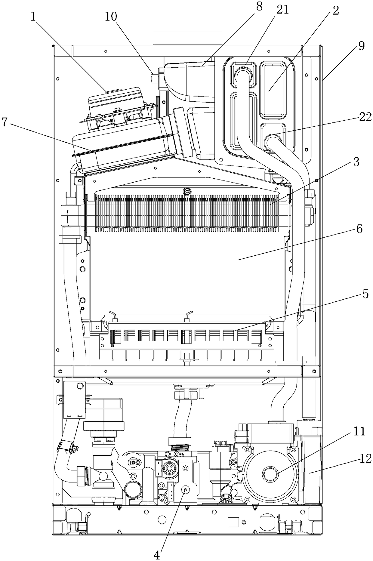
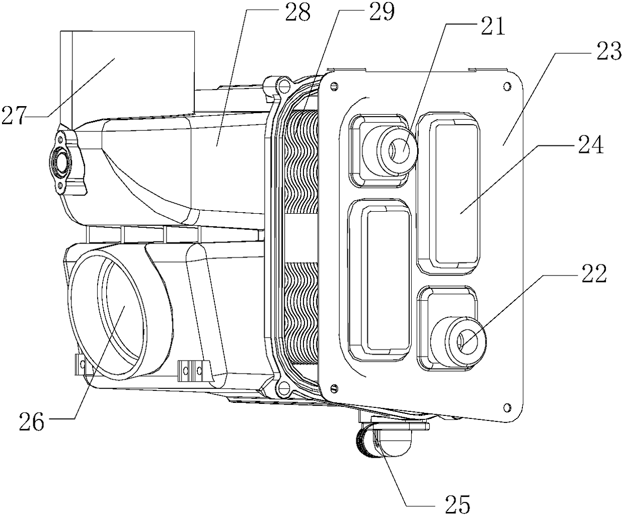
[0061]The waste heat recovery device 2 includes an outer shell, a condensation chamber formed in the outer shell, and a heat exchange device arranged in the condensation chamber. The heat exchange device has a first channel water inlet 21 and a second channel water outlet 22. The heat exchange device includes multiple stainless steel heat exchange tubes arranged side by side and stainless steel fins 29 fixed on the stainless steel heat exchange tubes. The outer casing includes a main casing 28 and a side cover 23 fixed to the main casing 28 by screws. The side cover 23 is provided with a water box 24 that is punched from the inside of the outer casing to the outside of the outer casing to form a convex water box. Two adjacent tubes of the stainless steel heat exchange tubes are connected to the water box 24 on one side of the side cover 23 for diversion of the water flow in the heat exchange device.

[0062] The heat exchange tubes and fins are made of stainless steel. Specifi...


PUM


Abstract

The invention discloses a condensation type gas heating stove. The condensation type gas heating stove comprises a main heat exchanger, a combustor, a combustion cavity, a smoke collection cover and acircular water pump and further comprises direct-current draught fan subject to directional control through a magnetic field, a waste heat recycling device communicated with the direct-current draught fan and a condensate collecting device; the direct-current draught fan is communicated with the main heat exchanger through the smoke collection cover, the waste heat recycling device and the condensate collecting device are sequentially connected to form a first condensate recycling system. According to the condensation type gas heating stove, the first condensate recycling system formed through sequential connection of the waste heat recycling device and the condensate collecting device is used, the wind amount of the direct-current draught fan is controlled to increase the condensation effect of the stainless steel fin pipe waste heat recycling device on the condensate under the low power, the separated-out condensate water is drained into the condensate collection device, and the condensation efficiency and the waste heat utilization rate of the heating stove can be improved.

Description

technical field [0001] The invention relates to the field of water heaters, in particular to a condensing gas heating furnace. Background technique [0002] Some premixed "IP type" gas heating water heaters currently on the market basically use AC fans as the delivery unit for the air volume used for combustion. At the same time, the AC fan is also combined with the waste heat recovery module to promote the condensation effect of the waste heat recovery module. However, when the AC fan is used as a heating furnace fan, its speed is fixed or the adjustment range is narrow. When the heating furnace burns at different power levels, the air volume delivered by it will lead to inconsistent thermal efficiency of the heating furnace when burning at different power levels, which cannot be guaranteed. The air-fuel ratio is always kept at the optimal ratio state, and as the power decreases, the thermal efficiency will decrease, which will lead to waste of resources; at the same time, ...

Claims


Application Information

Patent Timeline
IPC IPC(8): F24H8/00F24H9/20
CPCF24H8/00F24H9/2035Y02B30/00
Inventor 孟令建郑涛曹立国靳德峰
Owner QINGDAO ECONOMIC & TECHN DEV ZONE HAIER WATER HEATER
Learn More