
Co-prime area array-based two-dimensional direction of arrival quick estimation method

A two-dimensional wave and area array technology, which is applied in the orientation device for determining the direction, the radio wave measurement system, the measurement device, etc., can solve the problem of low angular resolution, low estimation accuracy and angular resolution, and complex calculation of the two-dimensional Capon algorithm High resolution and other problems, to achieve the effect of improved resolution and detection accuracy, improved estimation accuracy, and reduced mutual coupling effect

Inactive Publication Date: 2018-07-31
PLA STRATEGIC SUPPORT FORCE INFORMATION ENG UNIV PLA SSF IEU
View PDF7 Cites 14 Cited by
  • Summary
  • Abstract
  • Description
  • Claims
  • Application Information

AI Technical Summary

Problems solved by technology

The two-dimensional estimation algorithm of the uniform surface array is adopted, among which the MUSIC method has high estimation accuracy and belongs to unbiased estimation, but the calculation complexity is high; the two-dimensional Capon algorithm and the two-dimensional ESPRIT algorithm sacrifice a small amount of precision on the basis of the model of the MUSIC algorithm. Reduce the computational complexity, but the angular resolution of the two-dimensional Capon algorithm is low, and the two-dimensional ESPRIT algorithm requires multiple subspace decompositions. When the number of samples is large, the computational complexity is still high, and the accuracy cannot be guaranteed
Traditional non-sparse uniform arrays are limited by factors such as antenna size and mutual coupling effects between array elements, resulting in low estimation accuracy and angular resolution

Method used


Image

  • Co-prime area array-based two-dimensional direction of arrival quick estimation method
  • Co-prime area array-based two-dimensional direction of arrival quick estimation method
  • Co-prime area array-based two-dimensional direction of arrival quick estimation method

Examples


Embodiment 1

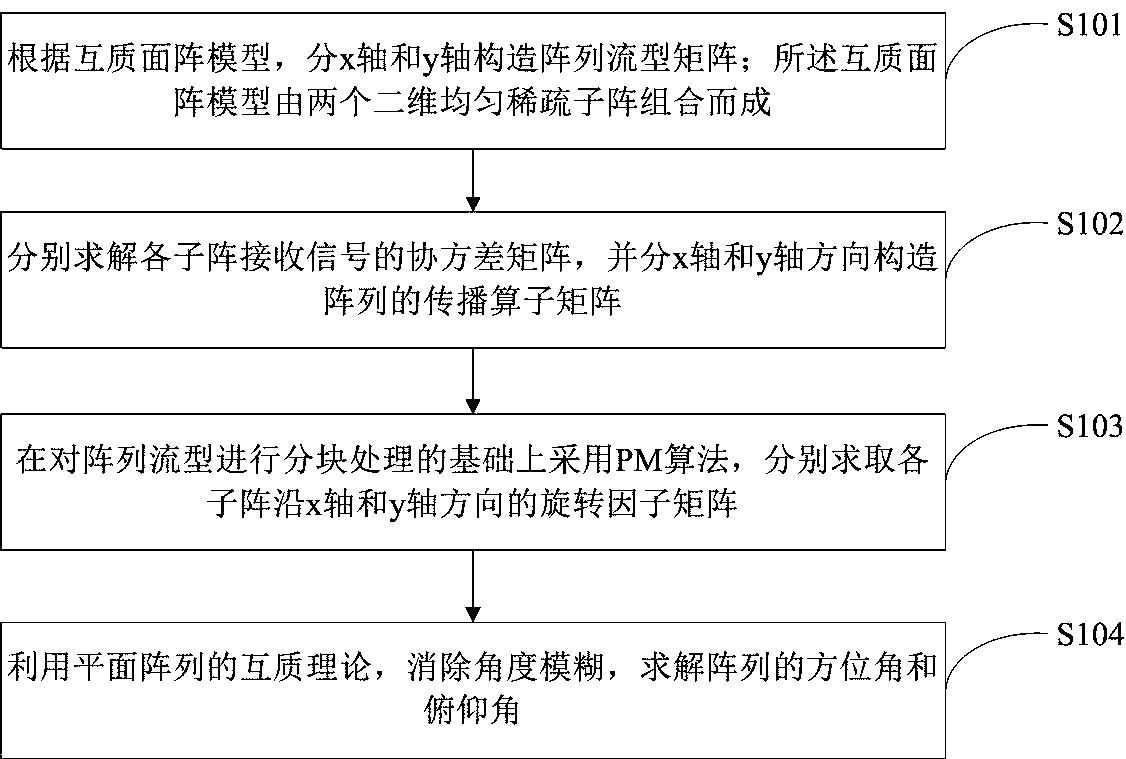
[0069] Such as figure 1 As shown, the two-dimensional direction of arrival fast estimation method based on the coprime array of the present invention includes the following steps:

[0070] Step S101: According to the coprime plane array model, the array flow pattern matrix is ​​divided into x-axis and y-axis; the coprime plane array model is composed of two two-dimensional uniform sparse sub-arrays;

[0071] The step S101 includes:

[0072] Step S1011: Construct the x-axis array manifold matrix of each sub-array;

[0073] Step S1012: Construct the y-axis array flow pattern matrix of each sub-array.

[0074] The step S101 is specifically as follows:

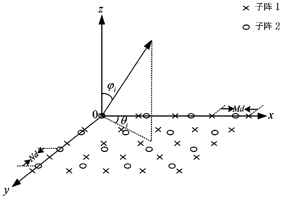
[0075] The number of receiving elements of the two-dimensional area array is N r '×N r ’, the array element spacing is d, d=λ / 2, λ is the wavelength of the incident signal, and the position of the kth array element relative to the reference array element is (x k ,y k ,z k ). Assuming that there are D far-field narrowband ...


PUM


Abstract

The invention belongs to the array signal processing technical field and relates to a co-prime area array-based two-dimensional direction of arrival quick estimation method. The co-prime area array-based two-dimensional direction of arrival quick estimation method includes the following steps that: of: array manifold matrixes are constructed on the basis of an x-axis and a y-axis respectively according to a co-prime area array model, two uniform sparse area arrays are combined so as to form the co-prime area array model; the covariance matrixes of the received signals of the sub-arrays are solved, the propagation operator matrixes of the arrays are constructed on the basis of the x-axis and the y-axis; a PM (Propagator Method) is adopted to solve the twiddle factor matrixes of the sub-arrays along the x-axis and y-axis on the basis of block processing performed on the array manifolds; and angle ambiguity is eliminated through using the co-prime theory of planar arrays, and the azimuthsand pitch angles of the arrays are solved. With the method of the invention adopted, low-complexity, high-precision and fuzzy-free joint estimation of the pitch angles and azimuth angles under the co-prime area array model can be realized.

Description

technical field [0001] The invention belongs to the technical field of array signal processing, in particular to a two-dimensional direction-of-arrival fast estimation method based on a coprime surface array. Background technique [0002] Two-dimensional direction-of-arrival estimation (direction-of-arrival, DOA) is a key technology to obtain target signal position information, which is widely used in radar, sonar, radio astronomy and other aspects. The two-dimensional direction of arrival estimation technology based on array signal processing is a passive positioning technology, which can obtain the azimuth and elevation angle of the target signal without transmitting test signals and without solving the prior information of the transmitted signals. At present, the two-dimensional DOA estimation technology based on the array mainly adopts three types of arrays, namely: L-shaped array, circular array and planar square array (abbreviated as area array). The direction-of-arri...

Claims


Application Information

Patent Timeline
IPC IPC(8): G01S3/00
CPCG01S3/00
Inventor 张彦奎代正亮巴斌王大鸣崔维嘉许海韵王振玉
Owner PLA STRATEGIC SUPPORT FORCE INFORMATION ENG UNIV PLA SSF IEU
Learn More