
Four-rotor permanent magnet switched reluctance motor

A permanent magnet switch and reluctance motor technology, which is applied in the direction of electrical components, electromechanical devices, and control/drive circuits. It can solve the problems of motor inoperability, winding magnetic field, and low work efficiency, and achieve the goal of increasing output power. Effect

Inactive Publication Date: 2018-07-31
唐平
View PDF2 Cites 0 Cited by
  • Summary
  • Abstract
  • Description
  • Claims
  • Application Information

AI Technical Summary

Problems solved by technology

[0002] The published application number is CN200410092870.2, and the name is repulsive permanent magnet (switch) reluctance motor. Its stator is composed of magnetically conductive casing and salient pole electromagnet; The permanent magnet is installed on the salient pole of the flower shaft, forming an effective flux air gap with the stator salient pole electromagnet; the rotor engages with the stator side cover plate through the bearing, so that the stator and the rotor are in relative motion with each other. The electromagnet core becomes the closed path of the permanent magnet magnetic circuit to generate mutual attraction force, the stator electromagnet magnetic field and the rotor permanent magnet magnetic field generate repulsive force when energized, and the two form a torque resultant force in the same direction, thereby dragging the rotor to move; in this way, according to a certain The sequence of turning on and off the stator electromagnetic winding, the rotor can run in a certain direction; the disadvantage of this motor is: when the stator is located in the middle of the salient poles of the two permanent magnets as shown in the figure, if the stator generates an N-pole magnetic field , the magnetic field will generate mutual repulsion to the N-pole permanent magnets on both sides of the magnetic field at the same time, and if the stator generates an S-pole magnetic field, the magnetic field will simultaneously generate mutual attraction to the N-pole permanent magnets on both sides of the magnetic field, so the motor is not working
[0003] In addition, the published application number is CN201010602154.X, and the name is a permanent magnet switched reluctance motor with distributed winding; it is composed of a stator and a rotor sleeved inside the stator. The surface of the inner ring is provided with evenly distributed stator teeth, and the surface of the rotor outer ring is provided with uniformly distributed rotor teeth. There is a gap between the mutually nested stator core and the rotor core, and the permanent magnet is embedded in the yoke of the stator core; the stator adopts The three-phase armature winding of distributed structure, there is only one winding coil between the adjacent stator slot bodies, every coil across two stator slots is connected to form a one-phase winding, and the mutual inductance between the three-phase windings is coupled with each other. There are always two-phase windings excited and energized at all times; the interaction output torque of the armature winding and the permanent magnet is greater than the output torque of the armature winding alone; the motor only adds two permanent magnets to the yoke of the traditional switched reluctance motor. Thus changing the magnetic field distribution and control mode, but because the winding magnetic field has not been fully utilized, the problem of low work efficiency has not been fundamentally solved

Method used


Image

  • Four-rotor permanent magnet switched reluctance motor
  • Four-rotor permanent magnet switched reluctance motor
  • Four-rotor permanent magnet switched reluctance motor

Examples


Embodiment Construction

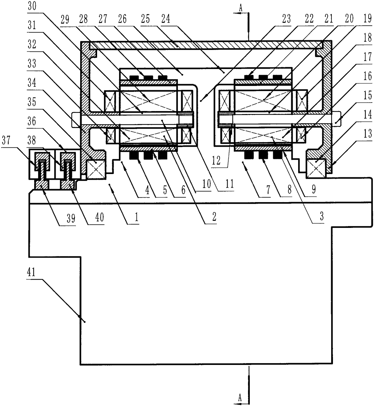
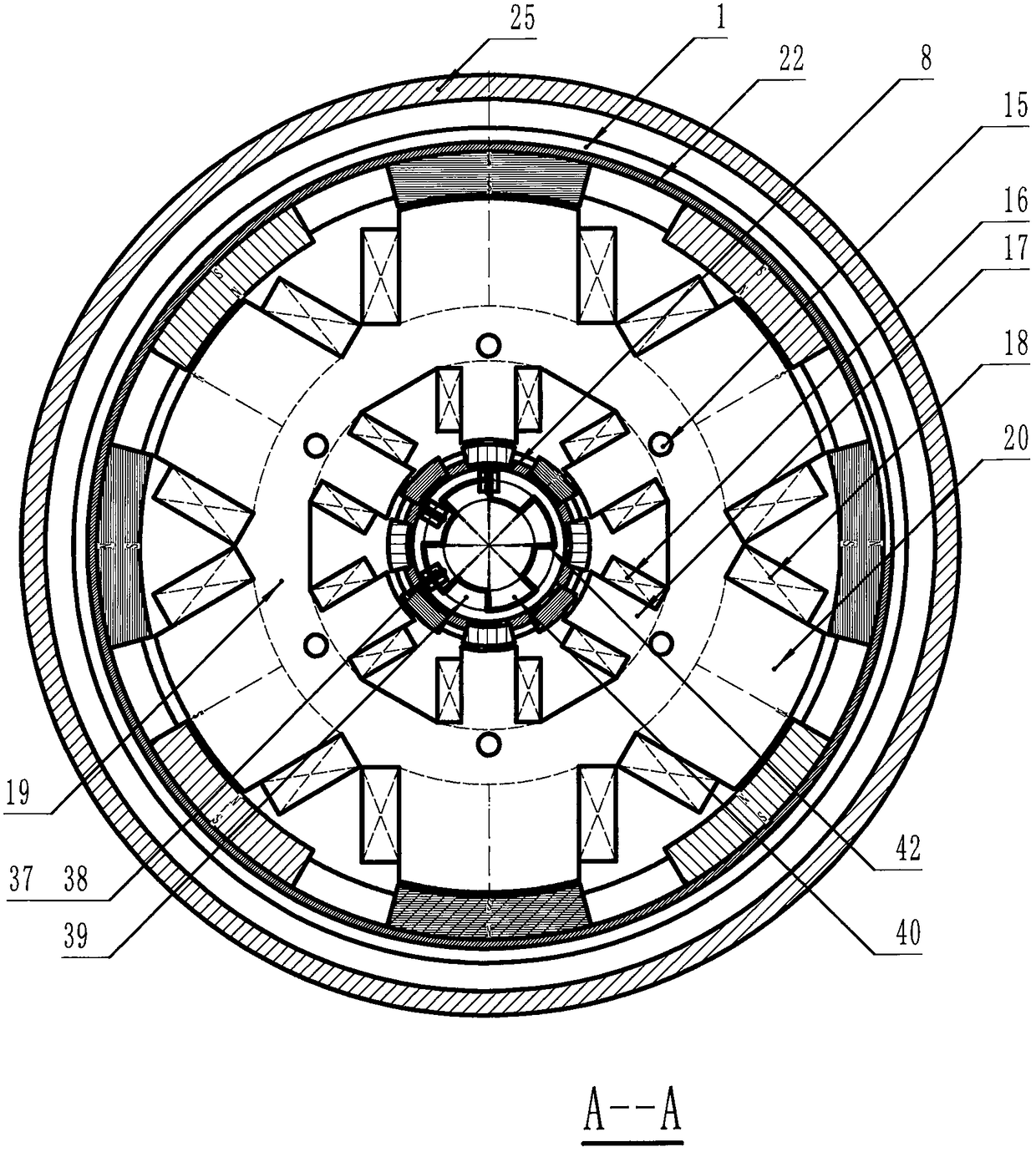
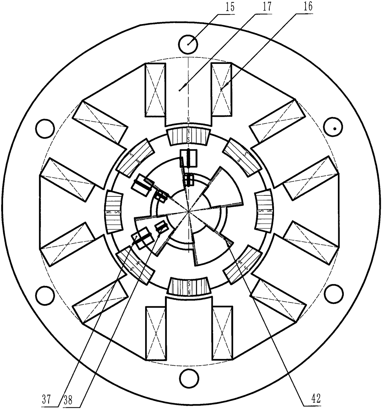
[0020] The four-rotor permanent magnet switched reluctance motor is composed of rotor 1, left stator 2, right stator 3, housing 41 and controller 43; Outer rotor 26, right inner rotor 7, right outer rotor 24, left inner magnetic sleeve 5, left outer magnetic sleeve 28, right inner magnetic sleeve 8, right outer magnetic sleeve 22, left inner magnetic steel ring 6, left The outer magnetic steel ring 27, the right inner magnetic steel ring 9, and the right outer magnetic steel ring 21 are composed of; wherein the left inner magnetic steel ring 6, the left outer magnetic steel ring 27, the right inner magnetic steel ring 9, and the right outer magnetic steel ring 21 The S pole and N pole of the magnetic steel are as Figure 10 All shown are arranged upside down; and the left inner magnetic sleeve 5, the left outer magnetic sleeve 28, the right inner magnetic sleeve 8, and the right outer magnetic sleeve 22 are used to connect the left inner rotor 4, the left outer rotor 26, The ...


PUM


Abstract

The invention discloses a four-rotor permanent magnet switched reluctance motor. The motor is formed by a rotor, a left stator, a right stator, a casing and a controller. The rotor is formed by a leftinner rotor, a left outer rotor, a right inner rotor and a right outer rotor. Each of the rotors has a magnetic steel ring with S pole magnet steels and N pole magnet steels in reverse arrangement ina ring. The left stator is installed on a left end cover, the right stator is installed on a right end cover, and each of the left stator and the right stator has inner windings, outer windings, inner pole teeth and outer pole teeth. Due to the introduction of the magnetic steels, with the design that the number of magnetic steel poles is larger than the number of stator pole tooth poles, while apole tooth magnetic field generates a suction force couple to an S pole magnetic field, the pole tooth magnetic field generates a repulsive force couple to an outer N pole magnetic field, thus an effect of double power is achieved by the pole tooth magnetic field, since the motor has four rotors, the output power of the motor is greatly raised compared with a motor with the same volume and weight, and the four-rotor permanent magnet switched reluctance motor is especially suitable for a condition with a high requirement of volume, weight and power ratios.

Description

technical field [0001] The invention relates to a four-rotor permanent magnet switched reluctance motor. Background technique [0002] The published application number is CN200410092870.2, and the name is repulsive permanent magnet (switch) reluctance motor. Its stator is composed of magnetically conductive casing and salient pole electromagnet; The permanent magnet is installed on the salient pole of the flower shaft, forming an effective flux air gap with the stator salient pole electromagnet; the rotor engages with the stator side cover plate through the bearing, so that the stator and the rotor are in relative motion with each other. The electromagnet core becomes the closed path of the permanent magnet magnetic circuit to generate mutual attraction force, the stator electromagnet magnetic field and the rotor permanent magnet magnetic field generate repulsive force when energized, and the two form a torque resultant force in the same direction, thereby dragging the rotor...

Claims


Application Information

Patent Timeline
IPC IPC(8): H02K16/00H02K11/33
CPCH02K16/00
Inventor 唐平
Owner 唐平
Learn More