Substrate support assembly with deposited surface features

A countertop, ceramic technology, applied in the field of substrate support components, can solve the problem of particle pollution

Active Publication Date: 2018-07-31
APPLIED MATERIALS INC
View PDF7 Cites 0 Cited by
  • Summary
  • Abstract
  • Description
  • Claims
  • Application Information

AI Technical Summary

Problems solved by technology

Trapped particles and broken spikes can cause particle contamination on the backside of the held wafer during processing

Method used


Image

  • Substrate support assembly with deposited surface features
  • Substrate support assembly with deposited surface features
  • Substrate support assembly with deposited surface features

Examples


Embodiment Construction

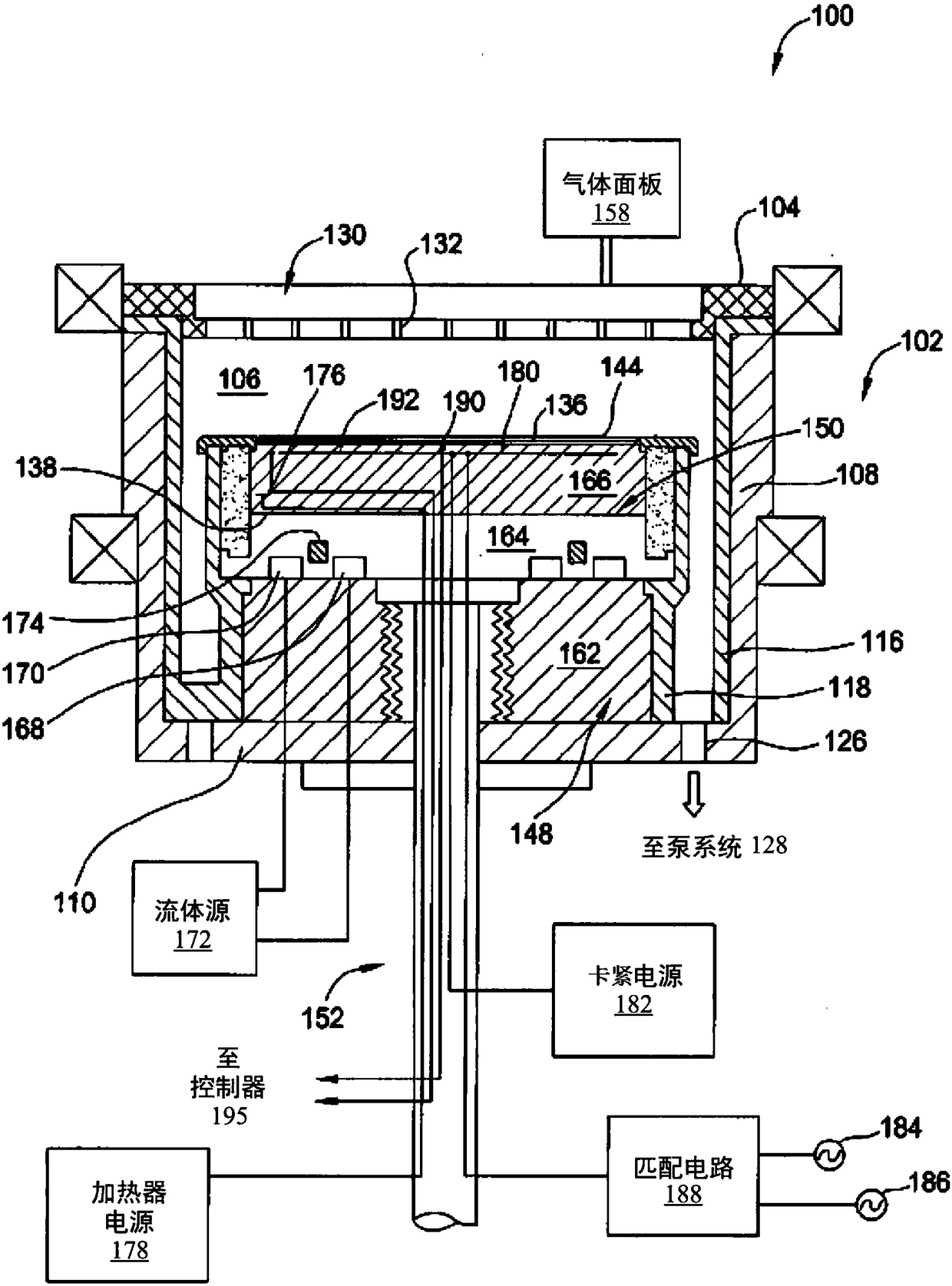
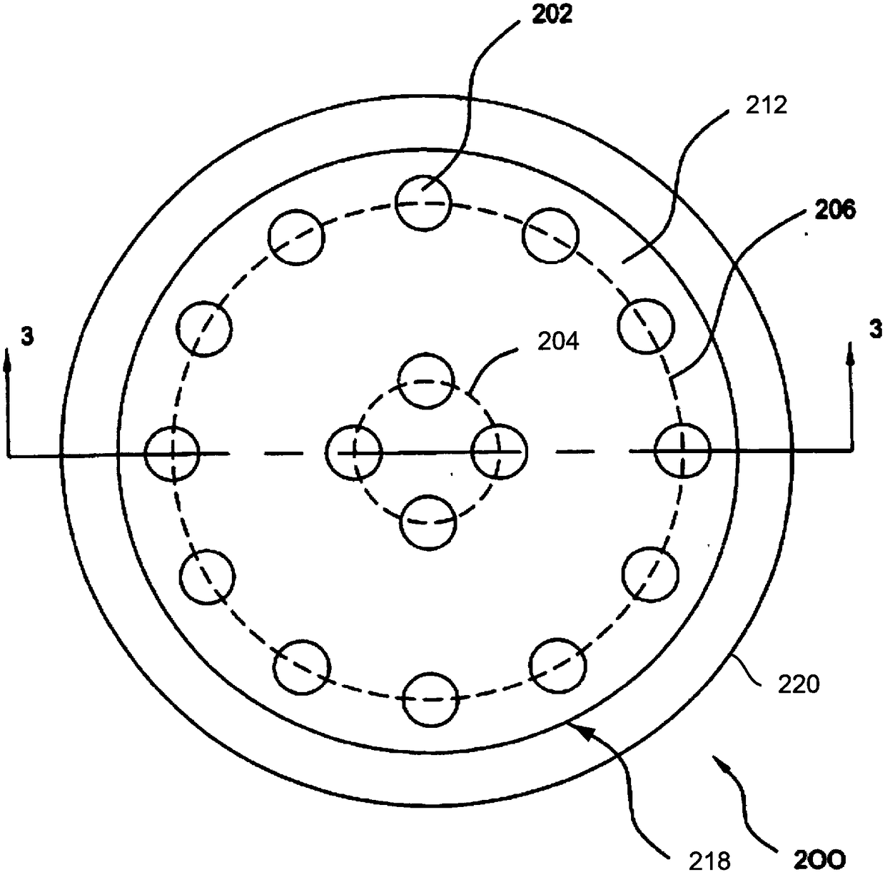
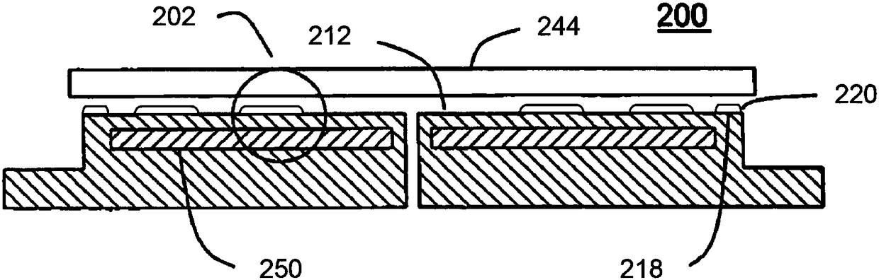
[0016] Embodiments of the present invention provide a substrate support assembly (eg, an electrostatic chuck) having a deposition table with rounded edges. Embodiments also provide a substrate support assembly having a protective ceramic coating formed over a ceramic body of the substrate support assembly. The protective ceramic coating can provide plasma corrosion resistance for protecting the ceramic body. Mesa can be deposited on top of the protective ceramic coating and also be resistant to plasma corrosion.

[0017] In one embodiment, an electrostatic chuck includes a thermally conductive base (eg, a metal or metal alloy base) and a ceramic body (eg, an electrostatic puck) bonded to the thermally conductive base. A protective ceramic coating serving as a protective layer covers the surface of the ceramic body, and a number of elliptical (eg circular) mesas are disposed over the protective ceramic coating. In one embodiment, an electrostatic chuck is fabricated by first ...


PUM

PropertyMeasurementUnit
Thicknessaaaaaaaaaa
Diameteraaaaaaaaaa
Thicknessaaaaaaaaaa

Abstract

A method of manufacturing an electrostatic chuck includes polishing a surface of a ceramic body of the electrostatic chuck to produce a polished surface and depositing a ceramic coating onto the polished surface of the ceramic body to produce a coated ceramic body. The method further includes disposing a mask over the coated ceramic coating, the mask comprising a plurality of elliptical holes anddepositing a ceramic material through the plurality of elliptical holes of the mask to form a plurality of elliptical mesas on the coated ceramic body, wherein the plurality of elliptical mesas have rounded edges. The mask is then removed from the coated ceramic body and the plurality of elliptical mesas are polished.

Description

technical field [0001] Embodiments of the invention generally relate to substrate support assemblies, such as electrostatic chucks, having a plasma-resistant protective layer with deposited surface features. Background technique [0002] In the semiconductor industry, devices are fabricated by several fabrication processes that produce structures of ever-decreasing size. Some fabrication processes, such as plasma etch and plasma clean processes, expose substrate supports such as electrostatic chucks (ESCs) (e.g., exposing the edges of the ESC during wafer processing and during chamber cleaning). Expose the entire ESC) to a high velocity plasma stream to etch or clean the substrate. Plasmas can be highly corrosive and can corrode processing chambers and other plasma-exposed surfaces. [0003] ESCs typically have surface features formed by placing a positive mask on the surface of the ESC, and then bead blasting the exposed portions of the ESC through the positive mask. A p...

Claims


Application Information

Patent Timeline
IPC IPC(8): H01L21/683H01L21/56H02N13/00B23Q3/15
CPCH01L21/68757H01L21/6833H01L21/6875H01L21/6831B23Q3/15H02N13/00G03F7/707C03C17/00H01L21/683H01L21/56H01L21/6835
Inventor 小温德尔·格伦·博伊德维贾伊·D·帕克赫郭塘坊丁震文
Owner APPLIED MATERIALS INC
Why Eureka
Try Eureka