
Alloy apparatus adjustable in clamping angle

An angle and alloy technology, used in metal processing machinery parts, clamping, metal processing equipment and other directions, can solve the problems of loose workpiece, low precision of processed parts, slow processing speed, etc., to achieve convenient long-distance automatic control, improve The effect of force structure and function diversification

Inactive Publication Date: 2018-08-03
WENZHOU ZHIJIE ELECTROMECHANICAL TECH CO LTD
View PDF0 Cites 2 Cited by
  • Summary
  • Abstract
  • Description
  • Claims
  • Application Information

AI Technical Summary

Problems solved by technology

[0002] When metal workpieces are processed, vises are generally used to fix the workpieces, but vises can only be used to fix regular types of workpieces. When processing workpieces with irregular shapes, the existing clamping equipment has the following problems: One is that it cannot be firmly clamped, resulting in slow processing speed and low work efficiency; the second is that even if the workpiece is barely fixed before cutting, the workpiece is prone to loosening during actual operation
Commonly used flat-nose pliers jaws are fixed, but the disadvantages are: for parts with irregular shapes, it is usually single-clamped, the processing efficiency is low, and the positioning accuracy in the direction perpendicular to the clamping direction is not high, resulting in the workpiece being processed low precision

Method used


Image

  • Alloy apparatus adjustable in clamping angle
  • Alloy apparatus adjustable in clamping angle
  • Alloy apparatus adjustable in clamping angle

Examples


Embodiment Construction

[0045] In the picture:

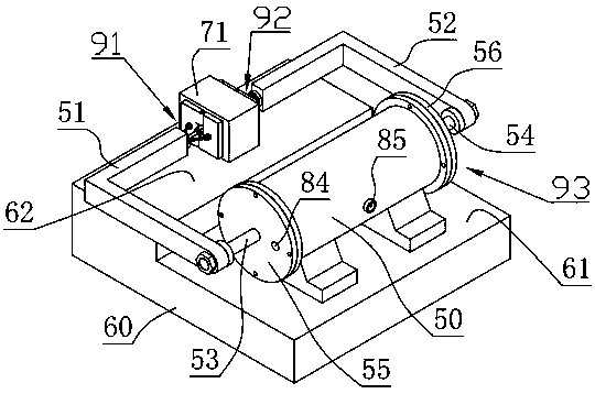
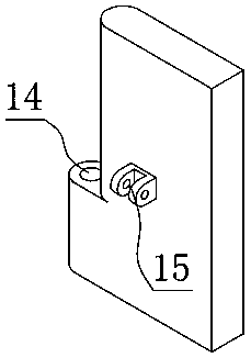
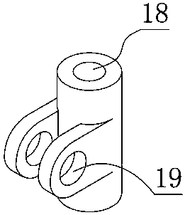
[0046] The first splint-10, the first swing hole-11, the first support hole seat-12, the second splint 13, the second swing hole-14, the second support hole seat 15, the angle pin-16, the support Sleeve-17, sleeve shaft hole-18, sleeve hole seat-19, first swivel base-20, swivel base shaft hole-21, swivel base swing hole-22, second swivel base-23, first Connecting rod-24, second connecting rod-25, hole seat sliding sleeve-26, left connecting rod hole seat-27, right connecting rod hole seat-28, hole seat sleeve inner hole-29, adjusting nut-30, nut Shaft shoulder section-31, nut cylindrical section-32, nut square shaft section-33, nut outer thread section-34, internal thread hole-35, lock nut-39, adjusting screw-40, adjusting hand wheel-41, Positioning nut-42, screw sleeve shaft pin-44, screw swing hole-47, hand wheel square hole-48, hydraulic cylinder-50, left support arm-51, right support arm-52, first piston- 53. The second piston-54, the first end c...


PUM


Abstract

The invention relates to a clamping apparatus for machining and an alloy apparatus adjustable in clamping angle. The alloy apparatus adjustable in clamping angle comprise a left supporting crank arm,a right supporting crank arm, a left clamping device, a right clamping device and a hydraulic driving device; and the two ends of the hydraulic driving device are provided with the piston rod end headof a first piston and the piston rod end head of a second piston correspondingly in a stretching manner. According to the improvement, the right clamping device and the left clamping device are in mirror symmetry, and the left supporting crank arm and the right supporting crank arm are in mirror symmetry; an adjusting hand wheel disk is adopted for driving a position adjusting nut to move forwards and backwards on an adjusting screw rod; by means of linkage of a first connection rod and a second connection rod, a work included angle can be formed between a first clamping plate and a second clamping plate around an included angle shaft pin, a cylinder body is clamped, and the stress structure is improved; and up-down free swinging and rotating around a screw rod sleeve shaft pin can also be achieved, an object on a bevel is effectively clamped, functions are comprehensive, and the alloy apparatus adjustable in clamping angle is practical and convenient; and the clamping faces of the first clamping plate and the second clamping plate are each plated with a layer of hard chromium alloy, and abrasion resistance and durability are better.

Description

[0001] Technical field The present invention relates to a machining clamping instrument, especially an alloy instrument with adjustable clamping angle. Background technique [0002] When metal workpieces are processed, vises are generally used to fix the workpieces, but vises can only be used to fix regular types of workpieces. When processing workpieces with irregular shapes, the existing clamping equipment has the following problems: One is that it cannot be firmly clamped, resulting in slow processing speed and low work efficiency; the second is that even if the workpiece is barely fixed before cutting, the workpiece is prone to loosening during actual operation. [0003] Flat nose pliers are clamping instruments used to clamp parts, and are necessary accessories for machine tools such as machining centers, milling machines and drilling machines. Commonly used flat-nose pliers jaws are fixed, but the disadvantages are: for parts with irregular shapes, it is usually single-c...

Claims


Application Information

Patent Timeline
IPC IPC(8): B23Q3/08C22C38/50C22C38/44C22C38/04C23C30/00
CPCB23Q3/082C22C38/002C22C38/04C22C38/44C22C38/50C23C30/00
Inventor 陈俞任
Owner WENZHOU ZHIJIE ELECTROMECHANICAL TECH CO LTD
Learn More