Clamping device for hydrogen detector sensor handle

A clamping device and detector technology, which is applied to workpiece clamping devices, heat treatment equipment, furnaces, etc., can solve the problems of cumbersome bundling operations, easy loosening of the hydrogen detector sensor clamping device, and inability to meet the needs of on-site use. , to achieve the effect of maintaining stability

Pending Publication Date: 2018-08-03
马鞍山马钢华阳设备诊断工程有限公司
View PDF0 Cites 0 Cited by
  • Summary
  • Abstract
  • Description
  • Claims
  • Application Information

AI Technical Summary

Problems solved by technology

[0006] The purpose of the present invention is to overcome the deficiencies in the prior art that the hydrogen detector sensor clamping device is easy to loosen, the binding operation is cumbersome, and cannot meet the needs of on-site use, and provides a hydrogen detector sensor handle clamping device that can be well Clamp the sensor handle of the hydrogen detector to meet the needs of different occasions at the same time. The structure is simple, easy to use, and suitable for popularization.

Method used


Image

  • Clamping device for hydrogen detector sensor handle
  • Clamping device for hydrogen detector sensor handle
  • Clamping device for hydrogen detector sensor handle

Examples


Embodiment 1

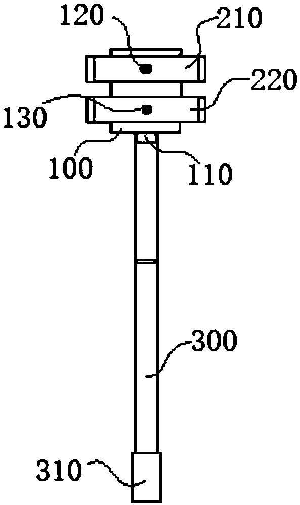
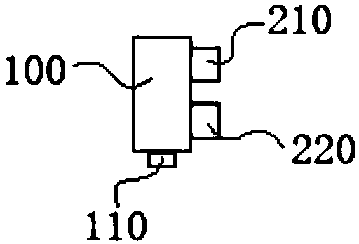
[0035] Such as Figure 1-Figure 3 As shown, a hydrogen detector sensor handle clamping device in this embodiment includes a clip base 100, an upper clip 210, a lower clip 220 and a telescopic rod 300, wherein the upper clip 210 and the lower clip 220 are respectively connected to the The upper and lower ends of the clip base 100 are connected, and the telescopic rod 300 is connected with the bottom end of the clip base 100 . Among them, the telescopic rod 300 can conveniently and quickly adjust the length of the rod, which can meet the height requirements of different positions on site. In this embodiment, the telescopic rod 300 can adopt a variety of existing conventional telescopic structures in the industry, which will not be described in detail here. For example, a multi-stage tubular structure can be used, and the expansion and contraction through pin holes and pins can be used. In this embodiment, the structure of the lower clip 220 is the same as that of the upper clip...

Embodiment 2

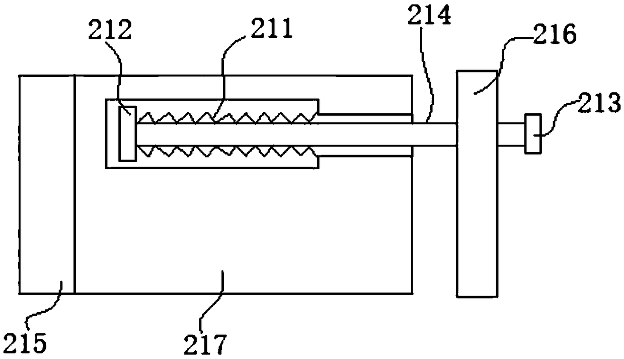
[0040] The basic structure of the hydrogen detector sensor handle clamping device of this embodiment is the same as that of Embodiment 1. Further, a return spring 211 is arranged in the adjustment hole in this embodiment, and one end of the return spring 211 is connected to the blocking part 212 for reset. The other end of the spring 211 is connected with the inner wall of the adjustment hole. Specifically, in this embodiment, the return spring 211 is sheathed on the outside of the pull rod 214 . One end of the pull rod 214 and the return spring 211 is connected to the blocking portion 212 to form a whole, and the other end of the return spring 211 is specifically fixed on the right side end wall of the large aperture section of the adjustment hole, as image 3 As shown in the middle position, pull the right baffle plate 216 to the right, that is, drive the pull rod 214 to move horizontally to the right side synchronously, and the blocking part 212 will move horizontally to th...

Embodiment 3

[0042] A hydrogen detector sensor handle clamping device of this embodiment has the same basic structure as that of Embodiment 2. Furthermore, a bolt hole is provided in the right side plate 216 of this embodiment, and a bolt hole corresponding to the bolt hole is provided at the right end of the pull rod 214. Cooperating threads, and the pull rod 214 passes through the bolt hole and is fixed by the nut 213. When installing, screw the threaded section at the right-hand side of the pull rod 214 into the bolt hole to the right, and fix it by the nut 213; The way of threaded connection is convenient and quick to use, and it is convenient for the disassembly and installation of the right side plate 216; secondly, by setting the nut 213, the clamping width of the upper clip 210 can be further fine-tuned, specifically, it can be clamped on the right side plate 216 After holding the sensor handle, lock the nut 213 to the left on the right side plate 216, which helps to further enhanc...


PUM


Abstract

The invention discloses a clamping device for a hydrogen detector sensor handle and belongs to the technical field of clamping devices. The clamping device for the hydrogen detector sensor handle comprises a clamp base, an upper clamp, a lower clamp and a telescopic rod. The upper clamp and the lower clamp are correspondingly connected with the upper end and the lower end of the clamp base, and the telescopic rod is connected with the bottom end of the clamp base. The clamping device for the hydrogen detector sensor handle aims at overcoming the defects that a clamping device for a hydrogen detector sensor is easy to loosen and cannot meet the demand of on-site use in the prior art. The clamping device for the hydrogen detector sensor handle can well clamp the hydrogen detector sensor handle and meanwhile meet the demand of different on-site occasions. The clamping device is simple in structure, convenient to use and suitable for popularization and application.

Description

technical field [0001] The invention relates to the technical field of clamping devices, in particular to a clamping device for a sensor handle of a hydrogen detector. Background technique [0002] The annealing furnace is an important equipment in the cold-rolled continuous hot-dip galvanizing production line. The atmosphere in the furnace is a reducing protective gas composed of nitrogen and hydrogen, which plays a role in reducing the surface of the strip steel and increasing the wettability of galvanizing in the production of the galvanizing line. , The quality of the atmosphere in the furnace is an important factor in determining the adhesion of the zinc layer, which directly affects the surface quality of the product. The quality of the atmosphere in the furnace depends largely on the airtightness of the furnace itself. During the normal production process, the annealing furnace must always maintain a slight positive pressure between 150-300Pa, so most of the furnace ...

Claims


Application Information

Patent Timeline
Patent Type & Authority Applications(China)
IPC IPC(8): B25B11/00C21D9/00
CPCC21D9/0006B25B11/00Y02T10/40
Inventor 刘健严思保庆永胜
Owner 马鞍山马钢华阳设备诊断工程有限公司
Why Eureka
Try Eureka