Optical fiber drawing and shearing machine with optical fiber coating storing function

A technology of optical fiber coating and shearing machine, applied in manufacturing tools, glass manufacturing equipment, etc., can solve the problems of low cutting efficiency, affecting work efficiency, complex structure, etc., and achieve the effect of high cutting efficiency, intelligent control and simple structure

Inactive Publication Date: 2018-08-03
NANTONG INST OF TECH
View PDF0 Cites 1 Cited by
  • Summary
  • Abstract
  • Description
  • Claims
  • Application Information

AI Technical Summary

Problems solved by technology

[0002] The optical fiber drawing and shearing machine with optical fiber coating storage is a machine that can straighten and cut the optical fiber. The existing optical fiber drawing and shearing machine with optical fiber coating storage has a complex structure and often requires manual control of optical fiber cutting. Smart low degree
Moreover, the cutting efficiency of the existing optical fiber drawing and shearing machine with optical fiber coating storage is low, which affects work efficiency

Method used

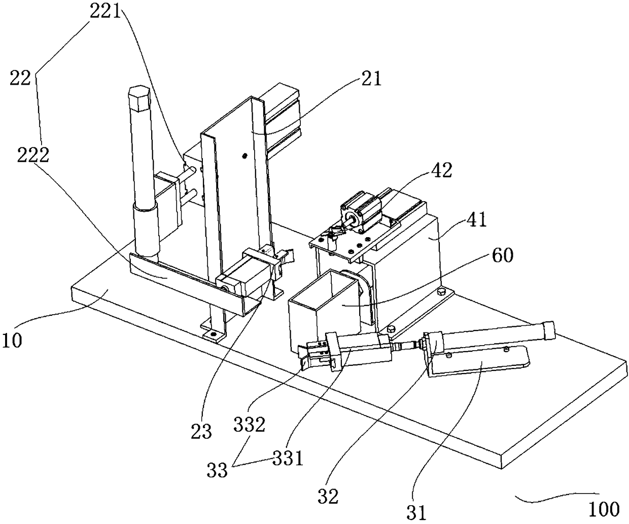
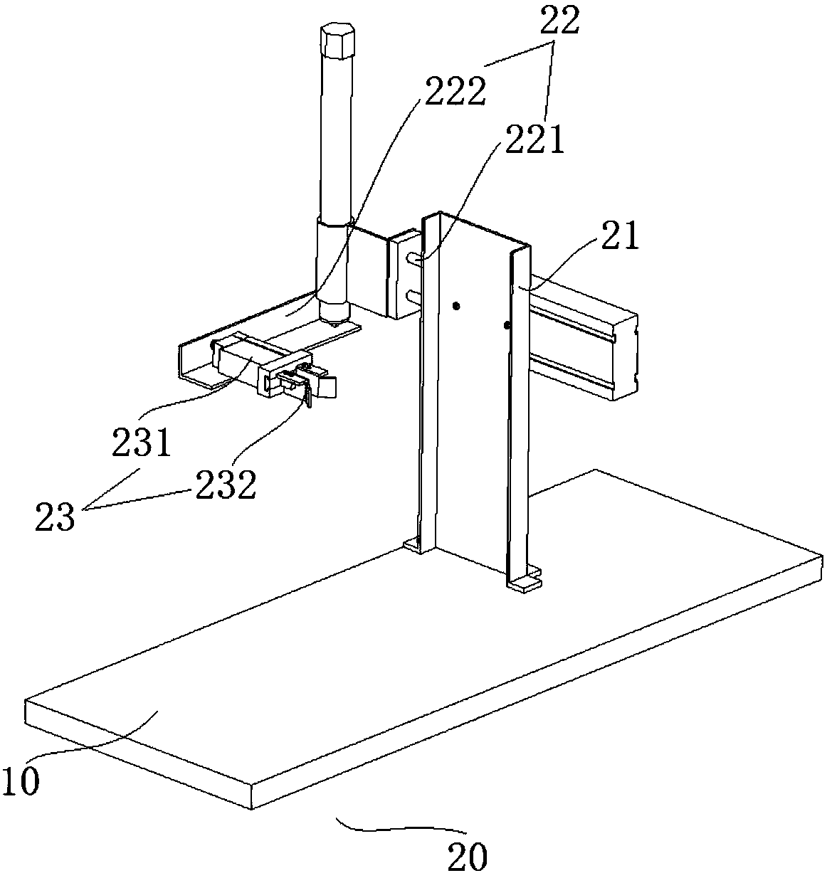
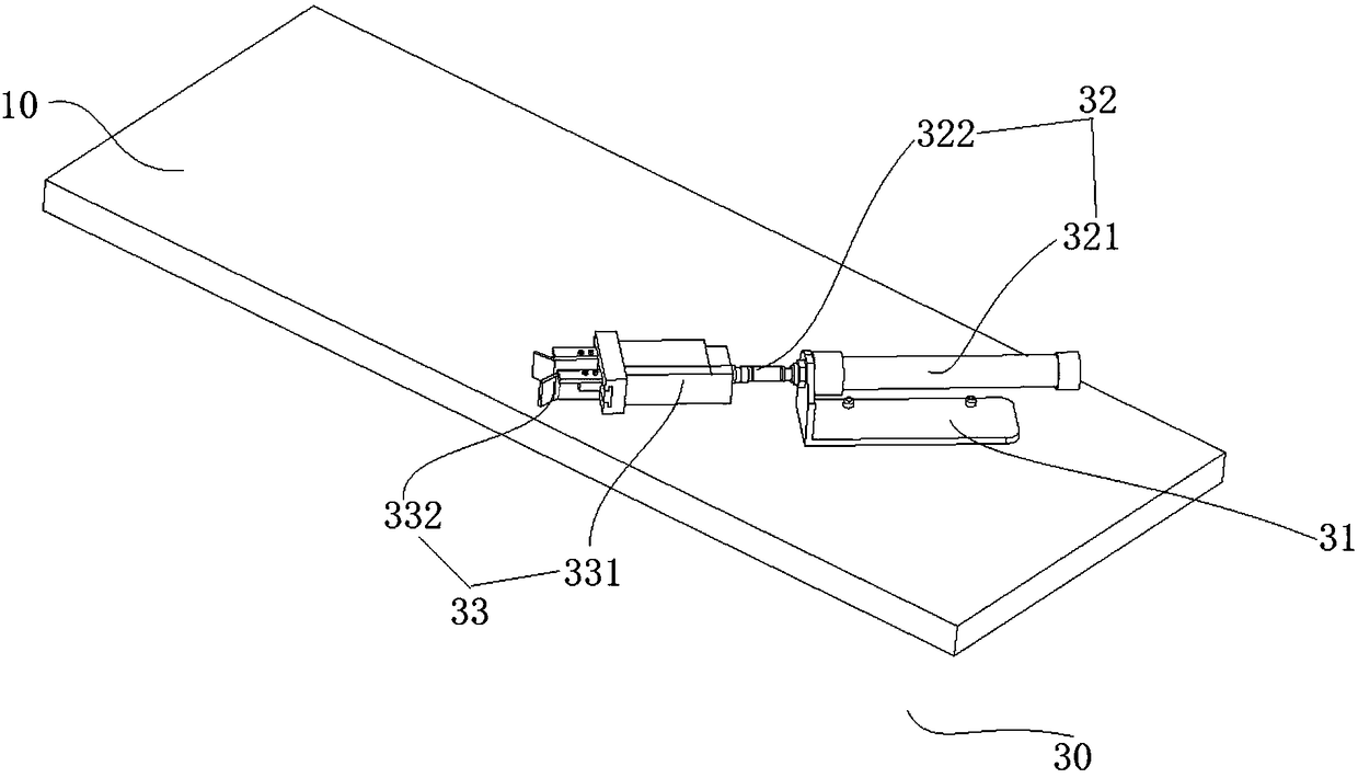

Image

  • Optical fiber drawing and shearing machine with optical fiber coating storing function
  • Optical fiber drawing and shearing machine with optical fiber coating storing function
  • Optical fiber drawing and shearing machine with optical fiber coating storing function

Examples


Embodiment Construction

[0058] In order to make the purpose, technical solutions and advantages of the embodiments of the present invention more clear, the following will clearly and completely describe the technical solutions of the embodiments of the present invention in conjunction with the drawings of the embodiments of the present invention. Apparently, the described embodiments are some, not all, embodiments of the present invention. All other embodiments obtained by those skilled in the art based on the described embodiments of the present invention belong to the protection scope of the present invention.

[0059] Unless otherwise defined, the technical terms or scientific terms used in the present invention shall have the usual meanings understood by those skilled in the art to which the present invention belongs. "First", "second" and similar words used in the present invention do not indicate any order, quantity or importance, but are only used to distinguish different components. Likewise...


PUM


Abstract

The invention provides an optical fiber drawing and shearing machine with an optical fiber coating storing function. The optical fiber drawing and shearing machine with the optical fiber coating storing function is used for shearing an optical fiber, and comprises a mounting seat, a first clamping mechanism, a second clamping mechanism, a shearing mechanism and a power supply assembly, wherein thefirst clamping mechanism and the second clamping mechanism are arranged on the mounting seat in a spacing manner; the first clamping mechanism and the second clamping mechanism are used for clampingthe optical fiber to be sheared respectively; the shearing mechanism is arranged on the mounting seat; the shearing mechanism is positioned between the first clamping mechanism and the second clampingmechanism so as to shear the optical fiber when the first clamping mechanism and the second clamping mechanism clamp the optical fiber to be sheared respectively; the power supply assembly is connected with the first clamping mechanism, the second clamping mechanism and the shearing mechanism respectively so as to supply power. According to the optical fiber drawing and shearing machine with theoptical fiber coating storing function, provided by the embodiment of the invention, through cooperation of the first clamping mechanism, the second clamping mechanism and the shearing mechanism, theoptical fiber to be sheared can be effected sheared; the optical fiber drawing and shearing machine with the optical fiber coating storing function is simple in structure, intelligent in control and high in shearing efficiency.

Description

technical field [0001] The present invention relates to the technical field of optical fiber cutting, and more specifically, relates to an optical fiber drawing and shearing machine with optical fiber coating storage. Background technique [0002] The optical fiber drawing and shearing machine with optical fiber coating storage is a machine that can straighten and cut the optical fiber. The existing optical fiber drawing and shearing machine with optical fiber coating storage has a complex structure and often requires manual control of optical fiber cutting. Smart The degree of transformation is not high. Moreover, the cutting efficiency of the existing optical fiber drawing and shearing machine with optical fiber coating storage is low, which affects work efficiency. Contents of the invention [0003] In view of this, the present invention provides an optical fiber drawing and shearing machine with optical fiber coating storage. [0004] In order to solve the problems o...

Claims


Application Information

Patent Timeline
IPC IPC(8): C03B37/16
CPCC03B37/16
Inventor 林盛昌王世光张峻维李志刚王治庆
Owner NANTONG INST OF TECH
Why Eureka
Try Eureka