Flow guiding and flow whirling integrated blade grid type device and combustion chamber

A technology of swirling blades and swirling flow, which is applied in the field of engines to achieve the effects of simple structure, improved circumferential distribution, and avoiding total pressure loss

Active Publication Date: 2018-08-03
NANJING UNIV OF AERONAUTICS & ASTRONAUTICS +1
View PDF5 Cites 3 Cited by
  • Summary
  • Abstract
  • Description
  • Claims
  • Application Information

AI Technical Summary

Problems solved by technology

However, the ram bypass of the afterburner / ram combustor does not have a ready-made swirl source, and it is necessary to add a corresponding swirl device in the flow channel, which will inevitably bring additional flow loss. Therefore, how to generate swirl with low resistance and high efficiency Flow is the key problem to be solved in the swirl combustor

Method used


Image

  • Flow guiding and flow whirling integrated blade grid type device and combustion chamber
  • Flow guiding and flow whirling integrated blade grid type device and combustion chamber
  • Flow guiding and flow whirling integrated blade grid type device and combustion chamber

Examples


Embodiment Construction

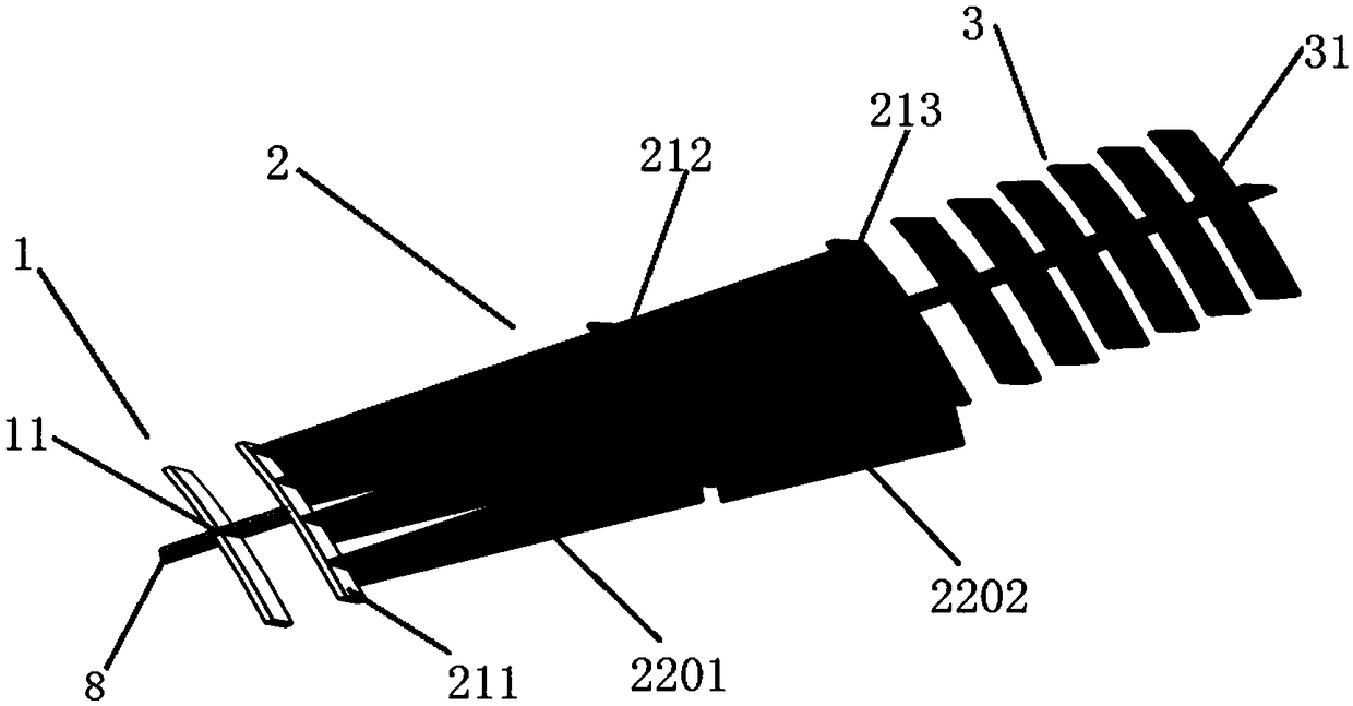
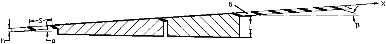
[0026] Such as figure 1 As shown, the integrated cascade device of the present invention, which integrates flow guide and swirl flow, includes a front cascade section 1 connected in sequence, a swirl section 2 for changing the flow direction of the airflow and generating a partial tangential direction, and a rear cascade section 2 The cascade section 3; the front cascade section 1 includes a first conical deflector 11; the rear cascade section 3 includes 6 second conical deflectors 31 coaxially arranged front and rear, the present invention the longitudinal index figure 2 in the X direction. The spacing S between the frustum-shaped deflectors gradually decreases from the first frustum-shaped deflector to the second frustum-shaped deflector, in order to generate different flow resistances to the airflow in the longitudinal direction. In this embodiment , the ratio of the spacing between the frustum-shaped deflectors to the length of the cascade device is reduced from 7% to 3...


PUM


Abstract

The invention provides a flow guiding and flow whirling integrated blade grid type device and a combustion chamber. The blade grid type device comprises a front blade grid section, a flow whirling section and a rear blade grid section, wherein the flow whirling section is connected with the front blade grid section and is used for making air flow generate partial tangent flowing; the rear blade grid section is connected with the other end of the flow whirling section; the front blade grid section comprises at least one first circular platform-shaped flow guide plate; and the rear blade grid section comprises at least one second circular platform-shaped flow guide plate. The blade grid type device provided by the invention implements distribution of inlet flow of the combustion chamber by utilizing the flow guide plates of the front and rear blade grid sections and forms reasonable and uniform centrifugal force distribution of the combustion chamber by utilizing rotational flow generated by the flow whirling section so as to enhance oil and gas mixing and promote flame propagation. The combustion chamber which utilizes the blade grid type device is simplified in structure and is reduced in weight, so the thrust-weight ratio of an engine is increased.

Description

technical field [0001] The invention relates to an engine, in particular to a combustion chamber in the engine and a vane cascade device integrating flow guiding and swirling flow therein. Background technique [0002] With the continuous expansion of flight speed and flight airspace, the performance requirements of the engine are increasing day by day, and the working conditions of the modern high-performance afterburning / ramming combustor have greatly changed compared with the previous combustion chamber. [0003] The airflow velocity of the high-performance afterburning / ramming combustor can reach Ma0.4 or more, and even Ma0.6 in some areas. On the other hand, it is difficult for the ignition source formed in the wake area of ​​the stabilizer to spread around after ignition. Therefore, in order to achieve uniform distribution of fuel oil on the cross section and promote flame propagation, it is necessary to use a large number of streamlined blunt bodies such as support pl...

Claims


Application Information

Patent Timeline
Patent Type & Authority Applications(China)
IPC IPC(8): F23R3/14F23R3/28F23R3/58
CPCF23R3/14F23R3/28F23R3/58
Inventor 范育新缪俊杰翟文辉
Owner NANJING UNIV OF AERONAUTICS & ASTRONAUTICS
Why Eureka
Try Eureka