A high power fiber optic circulator based on curved fiber end cap

An optical fiber circulator and optical fiber end technology, which is applied to the coupling of optical waveguides, instruments, optics, etc., can solve the problems of limiting the power bearing capacity of the device, low coupling efficiency, and difficult installation and adjustment, and achieves lower temperature, high coupling efficiency, The effect of increasing the damage threshold

Active Publication Date: 2020-12-29
SHANGHAI FEIBO LASER TECH CO LTD
View PDF23 Cites 0 Cited by
  • Summary
  • Abstract
  • Description
  • Claims
  • Application Information

AI Technical Summary

Problems solved by technology

[0004] Prior art "An optical circulator based on optical fiber and lens array CN103955026B", "An optical circulator CN 103995319B", "Compact low crosstalk, three-port optical circulator EP0860731B1", "Bi-directional optical circulator and applications there of US6538815 ", "method and system for providing a simplified in-line optical circulator US 6782145", mainly based on the spatial coupling method of the lens, this coupling method is to add a lens to the end face of the optical fiber, so the structure is more complicated
Generally, a λ / 4 fiber self-focusing lens is used. The size and wavelength of the lens must match the fiber. If there is any deviation, the coupling efficiency will be low, and the quality of the spot will be poor, which will seriously cause loss of optical signals.
Therefore, this traditional coupling technology is difficult to install and adjust, and there is a bottleneck in the coupling efficiency. In particular, the heat generated by the coupling loss stimulates the damage of the fiber end face, which limits the power capacity of the device.

Method used


Image

  • A high power fiber optic circulator based on curved fiber end cap
  • A high power fiber optic circulator based on curved fiber end cap
  • A high power fiber optic circulator based on curved fiber end cap

Examples


Embodiment 1

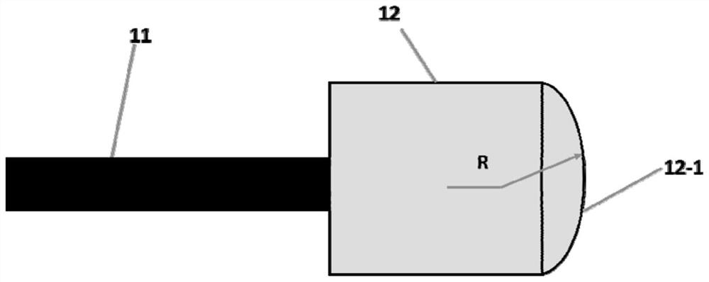
[0048] figure 1 It is the structure diagram of the optical fiber end cap based on the curved surface optical fiber end cap of the present invention, such as figure 1Said, including optical fiber (11) and end cap (12) and end cap curved surface (12-1), the radius of the curved surface of end cap is R, and end cap is cylindrical, and the output end surface of end cap is coated with anti-reflection film, for example: AR coating is SiO 2 , the coating band needs to match the working wavelength of the fiber optic circulator. The optical fiber and the curved end cap are connected through an integrated fusion splicing process. The optical fiber and the end cap are coaxial to ensure that the speed of light does not shift after entering, and the quality of the spot is improved, thereby improving the coupling efficiency.

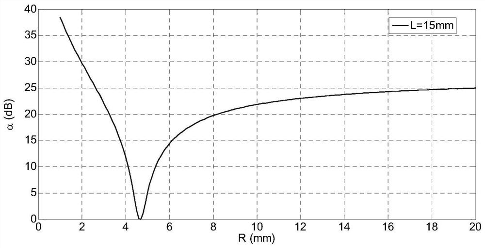
[0049] The radius of curvature R of the curved surface of the end cap needs to meet the following conditions:

[0050]

[0051] The radius of the laser beam wai...

Embodiment 2

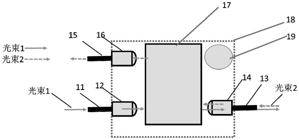
[0057] see image 3 , the fiber optic circulator includes an optical fiber (11) and an end cap (12), an optical fiber (13) and an end cap (14), an optical fiber (15) and an end cap (16), a circulator core (17), a substrate (18), Heat sink and thermal management system (not shown in the figure). The optical fiber (11) is connected to the end cap (12), the optical fiber (13) is connected to the end cap (14), the optical fiber (15) is connected to the end cap (16), and the circulator core (17) is installed on the base plate (18), A heat dissipation device (19) and a heat management system are installed on the base plate. The circulator core includes at least one of a polarization beam splitter, a birefringent crystal, a wave plate, a rotator, and a beam shifter, or a combination thereof, and its circulator core (17) can make the beam entering it deflect or Displacement; The manufacturing method and conditions of the optical fiber and the end cap are the same as in embodiment 1,...

Embodiment 3

[0062] The manufacturing method and conditions of the optical fiber and the end cap used in this implementation are the same as those in Embodiment 1.

[0063] see Figure 4 , the optical fiber circulator comprises an optical fiber (11) and an end cap (12), an optical fiber (13) and an end cap (14), an optical fiber (15) and an end cap (16), an optical circulator core (104), a cooling device (Fig. not shown), the optical circulator core (104) includes a polarization beam splitter (100), a Faraday rotator (101), a wave plate (102), and a polarization beam splitter (103).

[0064] Beam 1 enters the optical fiber (11) and expands into a collimated beam through the curved surface of the end face (12), enters the circulator core, and then enters the curved surface of the end cap (14) to be coupled to the tail core output of the optical fiber (13), and the light beam 2 enters the optical fiber ( 13) After the curved surface of the end face (14) expands into a collimated beam, it en...


PUM


Abstract

The invention provides a high-power optical fiber circulator based on cambered optical fiber end caps. The circulator at least comprises an optical fiber (11) and an end cap (12), an optical fiber (13) and an end cap (14), an optical fiber (15) and an end cap (16), a circulator core and a substrate, wherein the optical fiber (11) is connected with the end cap (12); the optical fiber (13) is connected with the end cap (14); the optical fiber (15) is connected with the end cap (16); and the circulator core is mounted on the substrate and can deviate or displace beams entering the circulator core. According to the circulator, the expanding and collimation of the beams at the cambered end caps are achieved through a principle of waveguide beam expanding and cambered auto-collimation output; the cambered end caps collect and couple signal light to enter tail fiber cores; the integrated cambered optical fiber end caps effectively improve the coupling efficiency of the beams in the circulator; and the power handling ability of the optical fiber circulator is improved.

Description

technical field [0001] The invention relates to an optical passive device, especially a multi-port high-power optical fiber circulator. Background technique [0002] The optical circulator is an optical device with multi-port input and output non-reciprocity to control the propagation direction of the beam. The optical signal can only be transmitted along a specific port sequence in the device. When the transmission sequence of the optical signal is changed, its loss is great. , so the role of signal isolation can be achieved. [0003] Due to the sequential transmission characteristics of the optical circulator, it becomes an important device in two-way communication and laser transmission. Currently, optical circulators are widely used in laser systems, coherent detection and hydrophones. With the improvement of the power of fiber lasers, applications such as optical circulators with pigtail input and output combined with coherent detection of high-power fiber lasers have...

Claims


Application Information

Patent Timeline
Patent Type & Authority Patents(China)
IPC IPC(8): G02B6/27G02F1/09
CPCG02B6/272G02B6/2746G02F1/093
Inventor 李骁军
Owner SHANGHAI FEIBO LASER TECH CO LTD
Why Eureka
Try Eureka