Linear focus Raman scattering probe

A Raman scattering and linear focusing technology, used in Raman scattering, material excitation analysis, etc., can solve the problems of sample Raman signal distortion, damage to the sample, and increase in the surface temperature of the sample, so as to improve the light transmission efficiency and prevent damage. Effect

Inactive Publication Date: 2015-03-04
CHONGQING INST OF GREEN & INTELLIGENT TECH CHINESE ACADEMY OF SCI
View PDF10 Cites 10 Cited by
  • Summary
  • Abstract
  • Description
  • Claims
  • Application Information

AI Technical Summary

Problems solved by technology

An increase in laser power will inevitably lead to an increase in the surface temperature of the sample, and even damage the sample, resulting in distortion of the Raman signal of the sample

Method used


Image

  • Linear focus Raman scattering probe
  • Linear focus Raman scattering probe
  • Linear focus Raman scattering probe

Examples


Embodiment 1

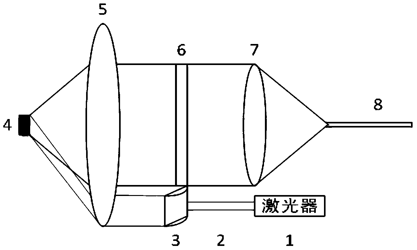
[0022] Such as figure 2 As shown, the linear focusing Raman scattering probe includes a laser light source 1, a laser transmission fiber 2, a linear cylindrical mirror lens group 3, a scattered light collection lens group 5, a narrow band-stop high-pass filter 6, and a parallel light converging lens group 7 And scattered light guide fiber 8.

[0023] The linear cylindrical mirror lens group 3 includes a collimator, a cylindrical mirror whose axes are perpendicular to each other and a converging lens,

[0024] The laser light emitted by the laser light source 1 is coupled to the laser transmission fiber 2, and then coupled to the linear cylindrical mirror lens group 3 through the laser transmission fiber 2 to form a parallel linear laser. The specific process of forming a parallel linear laser by the linear cylindrical mirror lens group is as follows:

[0025] The collimator transforms the Gaussian-distributed circular spot laser emitted by the laser into a square spot of par...

Embodiment 2

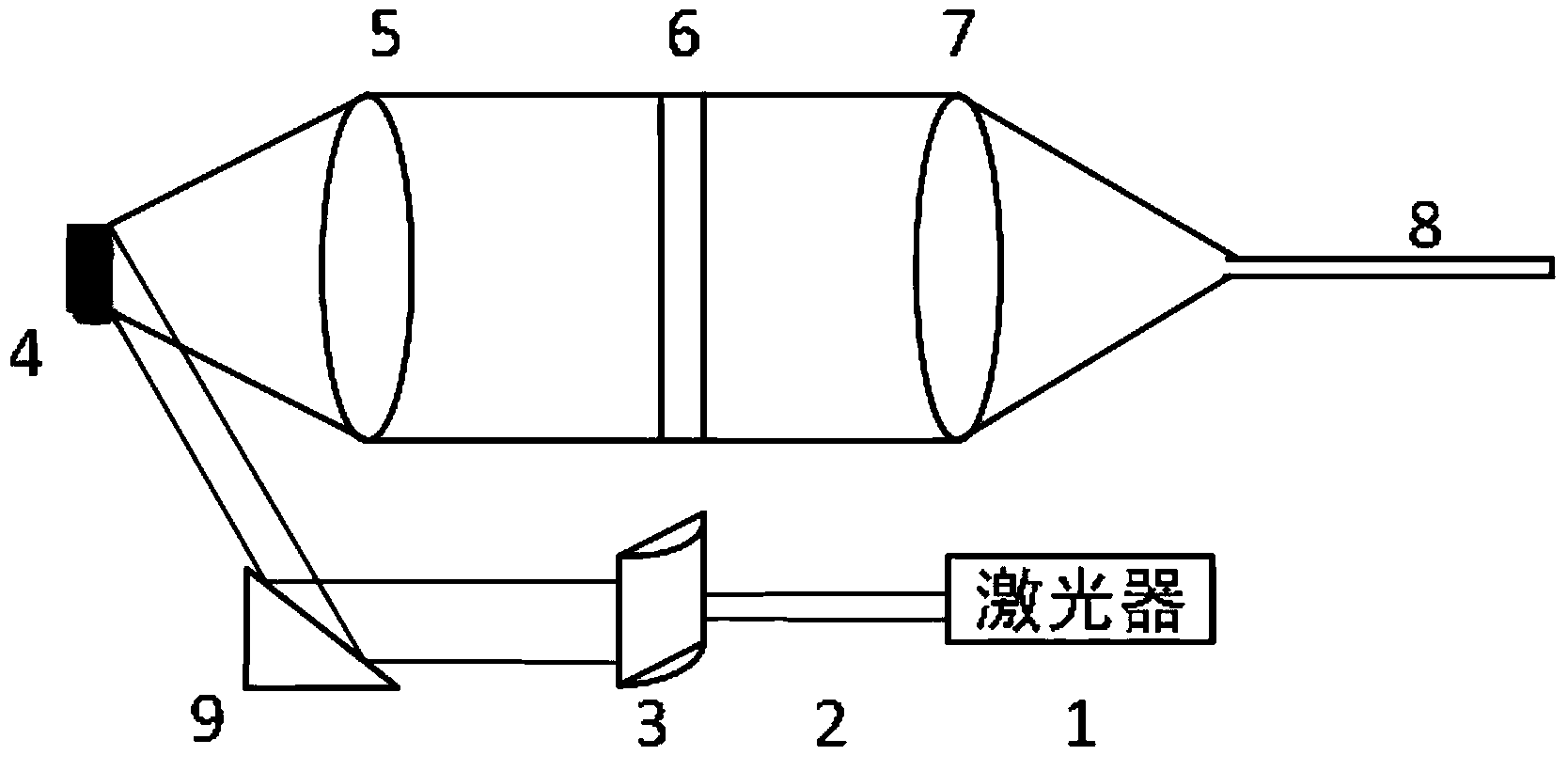
[0029] Such as image 3 As shown, in Embodiment 1, the parallel linear laser transmission device is a part of the scattered light collection lens group, the parallel linear laser transmission device in the present invention can also be a total reflection lens group 9, and the parallel linear laser light passes through the total reflection lens group and meets again Concentration on sample 4 also presents a linear spot.

[0030]Compared with the use of a part of the collection lens group as the parallel linear laser transmission device, the use of the total reflection lens group in this embodiment has the following advantages. Due to the side incident method, the line laser no longer passes through the scattered light collection lens, avoiding the The reflected laser light on the surface directly enters the collection lens, which greatly reduces the elastic scattering signal entering the scattered light collection lens, which not only reduces the optical density (OD) usage inde...


PUM

PropertyMeasurementUnit
diameteraaaaaaaaaa

Abstract

The invention discloses a linear focus Raman scattering probe. The linear focus Raman scattering probe comprises a laser conduction optical fiber 2, a linear cylindrical lens group 3, a scattered light collecting lens group 5, a narrowband resistance high-pass light filter 6, a parallel light converging lens group 7 and a scattered light conduction optical fiber 8, wherein laser is coupled to the linear cylindrical lens group 3 by the laser conduction optical fiber 2 and forms parallel linear laser through the linear cylindrical lens group 3; Raman scattered light is generated after the linear laser is reflected or converged to a sample; the scattered light collecting lens group 5 collects the scattered light from the surface of the sample; the scattered light enters the parallel light converging lens group 7 through the narrowband resistance high-pass light filter 6 and is coupled to the scattered light conduction optical fiber 8. According to the linear focus Raman scattering probe, Raman spectrum is guided in front of a slit of a spectrometer to form linear scattered light; the linear scattered light irradiates to the incident slit of the spectrometer is overlapped with the incident slit, so that the incident efficiency of the Raman spectroscopy is greatly improved; the sensitivity of a portable Raman spectrometer is improved.

Description

technical field [0001] The invention relates to an optical device, which can provide a high-efficiency laser Raman scattering detection head for a portable or hand-held Raman spectrometer. Background technique [0002] Raman scattering is an inelastic light scattering phenomenon produced by the interaction of single-frequency incident light and matter. Raman spectroscopy is a vibration spectrum with molecular fingerprint information, which can be used to quickly and accurately analyze and identify substances (or molecules). It has been widely used in the fields of physics, chemistry, materials, biology, medicine, food, archaeology and criminal investigation. Raman spectroscopy technology uses light as a probe. It has the characteristics of non-contact, non-destructive, real-time on-site, in-situ and minimal sample consumption, and has the advantages of high spatial resolution and high spectral resolution. In addition, Raman spectroscopy can be detected in conventional envi...

Claims


Application Information

Patent Timeline
Patent Type & Authority Applications(China)
IPC IPC(8): G01N21/65
Inventor 汤冬云刘玉龙张炜陈昭明方绍熙张华谢婉谊何石轩王雅冠刘崇武
Owner CHONGQING INST OF GREEN & INTELLIGENT TECH CHINESE ACADEMY OF SCI
Why Eureka
Try Eureka