Pulse stability control device and method of laser regeneration amplifier

A regenerative amplifier and stability control technology, which is applied in the laser field to solve the effects of poor pulse stability and low amplification efficiency

Inactive Publication Date: 2018-08-03
HARBIN INST OF TECH
View PDF6 Cites 14 Cited by
  • Summary
  • Abstract
  • Description
  • Claims
  • Application Information

AI Technical Summary

Problems solved by technology

[0006] The deficiencies of the existing pulse train laser amplification system may not yet be realized: 1. Realize efficient amplification of pulse train laser; 2. Under the premise of ensuring pulse extraction efficiency, realize pulse train laser amplification with high pulse stability; 3. Different work Under the condition of repetition rate, the amplitude stability of pulse train laser remains consistent

Method used


Image

  • Pulse stability control device and method of laser regeneration amplifier

Examples


specific Embodiment approach 1

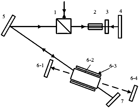
[0024] Specific Embodiment 1: This embodiment provides a pulse stability control device for a laser regenerative amplifier, such as figure 1 As shown, the pulse stability control device is sequentially provided with a polarization beam splitter prism 1, an electro-optic Q-switching switch 2, a 1 / 4 wave plate 3, a first plane mirror 4, a second mirror 5, a laser amplifier and a gain Control module, the third reflector 7, wherein:

[0025] The polarization splitter prism 1, the electro-optical Q-switching switch 2, the 1 / 4 wave plate 3, the first plane mirror 4, the second mirror 5, the laser amplification and gain control module, and the third mirror 7 jointly form a laser regenerative amplifier;

[0026] The first flat mirror 4, the second reflector 5 and the third reflector 7 constitute the resonant cavity of the laser regenerative amplifier;

[0027] The laser amplification and gain control module is composed of a fourth reflector 6-1, a laser crystal 6-2, an LD target bar ...

specific Embodiment approach 2

[0041] Embodiment 2: This embodiment provides a method for controlling the pulse stability of the laser regenerative amplifier using the device described in Embodiment 1. The method is implemented by the following steps:

[0042] Step 1: The S-polarized pulse train laser is incident into the laser regenerative amplifier through the polarization beam splitter prism 1. When there is no external voltage applied to the electro-optic Q-switch switch 2, the pulse train laser passes through the electro-optic Q-switch switch 2, 1 / 4 wave plate 3 and The first flat mirror 4, the laser optical polarization state is changed to P polarized light, and the pulse train laser is transmitted through the polarization beam splitter prism 1;

[0043] Step 2: Apply a 1 / 4 wave voltage to the electro-optic Q-switching switch 2. When the laser passes through the electro-optic Q-switching switch 2 and the 1 / 4 wave plate 3 again, the polarization state will not change, and the P-polarized pulse train las...


PUM


Abstract

The invention discloses a pulse stability control device and a method of a laser regeneration amplifier. The device comprises a polarization beam splitter prism, an electro-optical modulation Q switch, a 1 / 4 wave plate, a first plane mirror, a second reflector, a laser amplification and gain control module and a third reflector that jointly form the laser regeneration amplifier, wherein the firstplane mirror, the second reflector and the third reflecting mirror form a resonant cavity of the laser regeneration amplifier; the laser amplification and gain control module comprises a fourth reflector, a laser crystal, an LD target strip and a fifth reflector; and the fourth reflector, the laser crystal and the fifth reflector form a gain adjustment cavity. The efficient amplification of a multi-pulsed laser can be achieved; the pulse stability of output of the multi-pulsed laser is controlled by adjusting a gain in an amplification medium; and the high stability amplification of the multi-pulsed laser with different repetition frequencies is achieved.

Description

technical field [0001] The invention belongs to the technical field of lasers, and relates to a pulse stability control system and method for a pulse train regenerative amplifier. Background technique [0002] Plane Laser Induced Fluorescence (PLIF) is an imaging diagnostic technology based on a sheet laser beam that excites free radicals or tracer particles in the flow field to radiate fluorescence, and obtains the spatial distribution field information of the flow field by imaging the fluorescence. . Compared with traditional measurement methods, PLIF technology has the characteristics of non-contact measurement, high time (ns level) and space (mm level) resolution, and two-dimensional space measurement. High-speed PLIF technology can be applied to high-speed flow field and combustion field diagnosis, which is of great significance for promoting the development of a new generation of supersonic vehicles and attitude control engines. [0003] In order to meet the applicat...

Claims


Application Information

Patent Timeline
Patent Type & Authority Applications(China)
IPC IPC(8): H01S3/10H01S3/115H01S3/081H01S3/0941
CPCH01S3/10061H01S3/0815H01S3/0941H01S3/115
Inventor 闫仁鹏李旭东马欲飞樊荣伟董志伟陈德应刘志祥文晓林
Owner HARBIN INST OF TECH
Why Eureka
Try Eureka