
Telemetering system power supply device and control method for testing rotating member

A technology of telemetry system and power supply device, applied in circuit devices, battery circuit devices, different battery charging directions, etc., can solve the problems of limited installation space of rotating parts, low battery utilization rate, complex installation structure, etc., and improve stability. and interactivity, reduce design difficulty, and reduce the effect of hardware volume

Inactive Publication Date: 2018-08-03
AECC SICHUAN GAS TURBINE RES INST
View PDF6 Cites 3 Cited by
  • Summary
  • Abstract
  • Description
  • Claims
  • Application Information

AI Technical Summary

Problems solved by technology

[0002] At present, imported or domestic multi-channel telemetry systems have been applied in the parameter test of aero-engine rotating parts. Domestically, inductive power supply is generally used to provide non-contact power supply to the rotating part of the telemetry system. Its advantage is that it can be used for a long time. Continuous power supply, the disadvantage is that the power supply distance is limited (usually not greater than 5mm), and the installation structure is complicated
For some aeroengines with large axial movement of rotating parts, limited installation space of telemetry system, or aero-engines that require rapid installation of telemetry system, the form of inductive power supply cannot meet the test requirements
At present, some telemetry systems have adopted a battery-powered solution. Since the installation space of the rotating part of the telemetry system is very limited during the engine test, and it is not allowed to modify the hardware after installation, the usual method is to directly turn on the battery for output. This power supply method makes the battery utilization rate very low and uncontrolled

Method used


Image

  • Telemetering system power supply device and control method for testing rotating member
  • Telemetering system power supply device and control method for testing rotating member
  • Telemetering system power supply device and control method for testing rotating member

Examples


Embodiment Construction

[0029] The present invention is described in further detail below in conjunction with accompanying drawing:

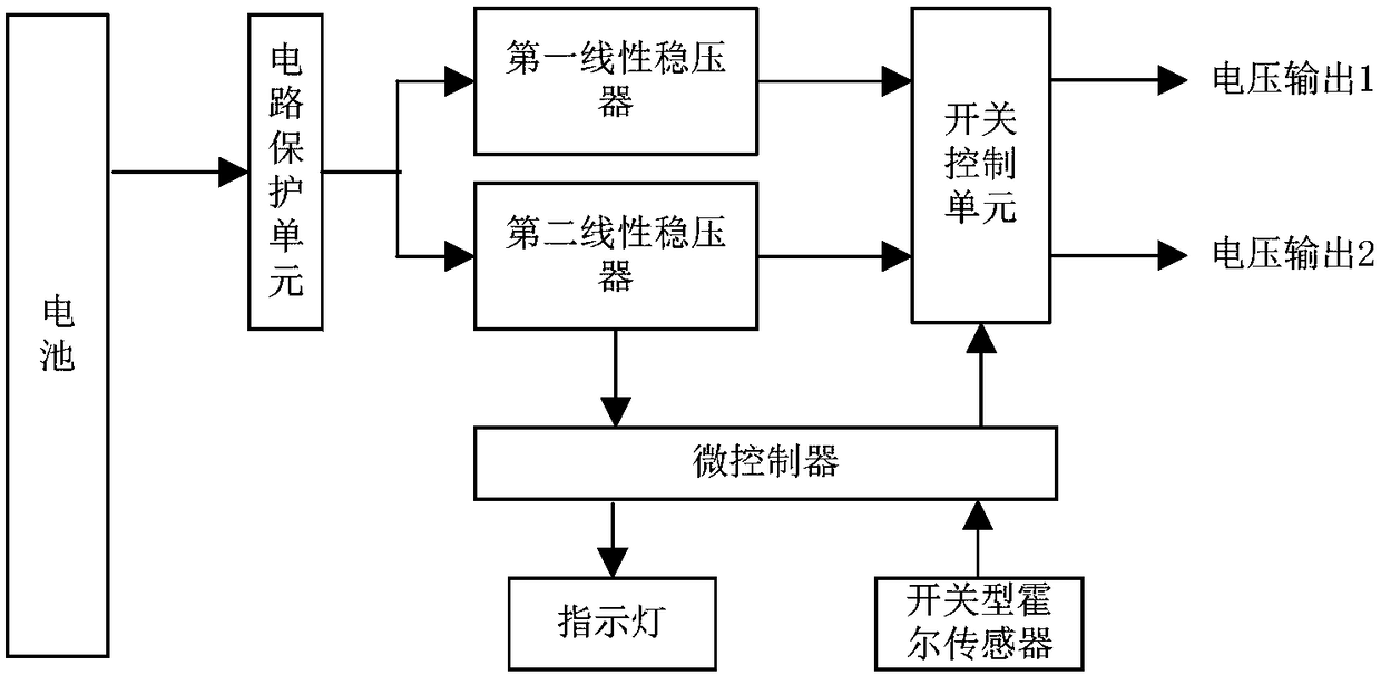
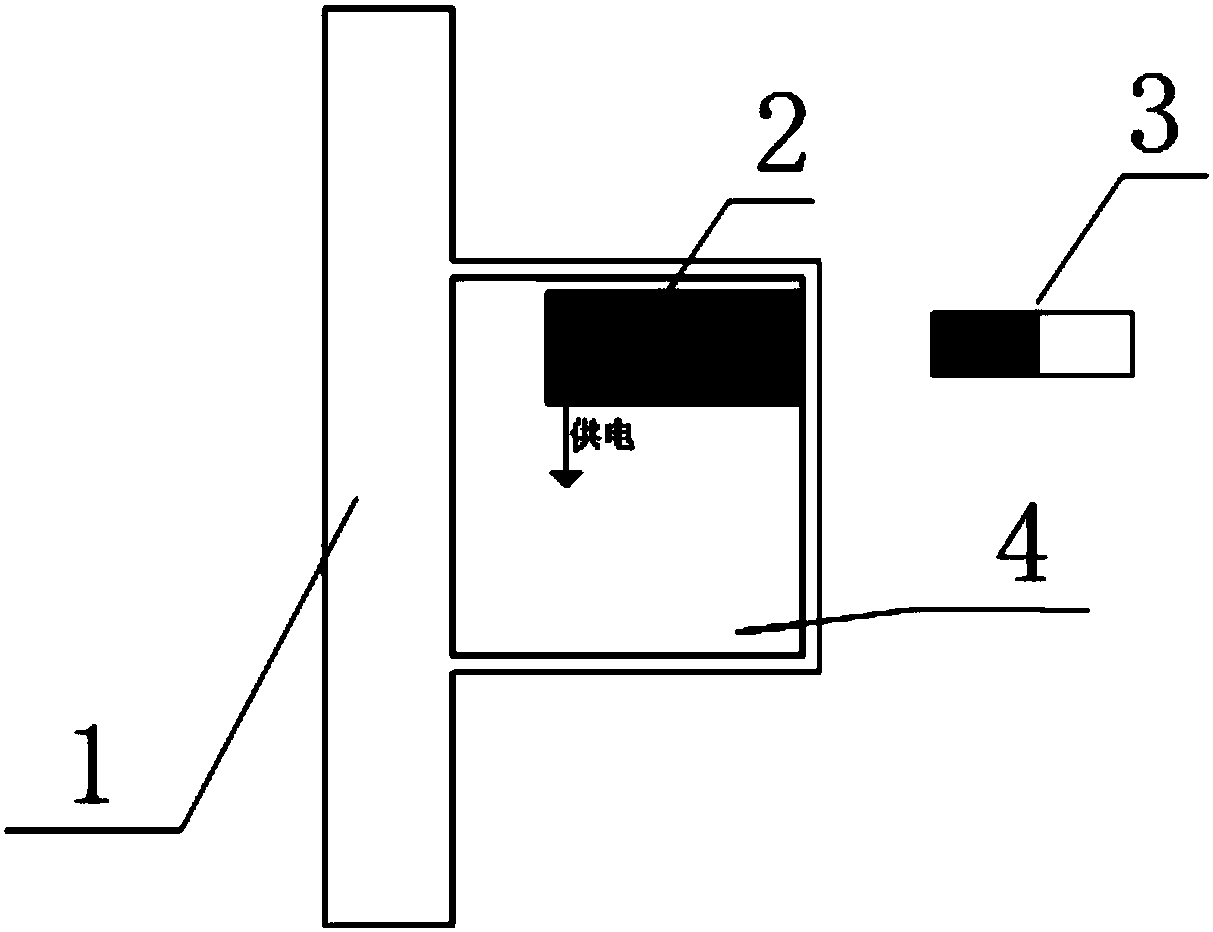
[0030] A telemetry system power supply device for rotating part test is an internal part of the telemetry system rotating part, which is responsible for providing electric energy. The device is modular and easy to replace during use; the device is non-contact controllable, and uses the method of changing the magnetic field strength around the device to perform non-contact control of the battery power output; the device has indicator light feedback, which can monitor the control action and battery power status Give instructional feedback. Its functional block diagram is as figure 2 shown.

[0031] The device includes a microcontroller, a circuit protection unit, a first linear voltage regulator, a second linear voltage regulator, a switch control unit, a switch-type Hall sensor, an indicator light and a battery in hardware.

[0032] As the digital processing and con...


PUM


Abstract

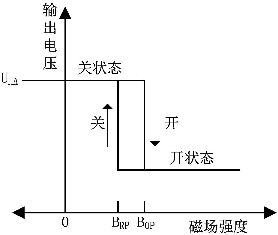
The invention provides a telemetering system power supply device and control method for testing a rotating member. According to the power supply device, a control panel is connected with a battery through lead bonding, wherein the control panel comprises a microcontroller, a circuit protection unit, a first linear voltage regulator, a second linear voltage regulator, a switch control unit, a hallswitch sensor and an indicator light; the microcontroller senses a magnetic field change through the hall switch sensor, outputs a control signal to the switch control unit and carries out real-time indication on the working state through the indicator light; and the microcontroller, the circuit protection unit and the first linear voltage regulator are combined to provide the control panel with apower supply. The control method comprises the steps of collecting magnetic intensity signals; screening data; outputting a control signal; and carrying out battery state monitoring and state indication. A difficulty in power supply control on the battery of a telemetering system rotating part for the rotating member is avoided, the design difficulty of hardware is reduced, the volume of the hardware is reduced, the power consumption of the hardware is reduced and the stability and the interactivity of the device are improved.

Description

technical field [0001] The invention belongs to the technical field of non-contact controllable power supply, and in particular relates to a power supply device and control method for a remote measurement system used for testing rotating parts of an aeroengine. powered by. Background technique [0002] At present, imported or domestic multi-channel telemetry systems have been applied in the parameter test of aero-engine rotating parts. Domestically, inductive power supply is generally used to provide non-contact power supply to the rotating part of the telemetry system. Its advantage is that it can be used for a long time. The disadvantage of continuous power supply is that the power supply distance is limited (usually not greater than 5mm), and the installation structure is complicated. For some aeroengines with large axial movement of rotating parts, limited installation space for telemetry systems, or aeroengines that require rapid installation of telemetry systems, the ...

Claims


Application Information

Patent Timeline
Patent Type & Authority Applications(China)
IPC IPC(8): H02J7/00H02J50/00H02J5/00
CPCH02J5/005H02J7/0047H02J7/025H02J50/00
Inventor 田青林李仙丽孙勇罗乘川李粮蔡沅颖苏曦之
Owner AECC SICHUAN GAS TURBINE RES INST
Learn More