Eureka AIR delivers breakthrough ideas for toughest innovation challenges, trusted by R&D personnel around the world.

Sectionalized flexible roll convexity regulation and control roller

A technology of flexible rolls and rolls, applied in the direction of rolls, metal rolling, metal rolling, etc., can solve the problems of difficult grinding of rolls, unmeasurable, and limited amount of roll crown adjustment, so as to solve the problems of roll wear and improve the strength of the rolls. The effect of shape control ability and roll stiffness improvement

Active Publication Date: 2018-08-07
YANSHAN UNIV
View PDF6 Cites 16 Cited by
  • Summary
  • Abstract
  • Description
  • Claims
  • Application Information

AI Technical Summary

Problems solved by technology

[0003] However, there are different problems in each of the above-mentioned technologies: the original roll crown roll of the CVC series has great limitations: first, the grinding of the roll is difficult, and the roll needs to be changed frequently; The specification adaptability of different strips is limited; third, the original convexity of the rolls will be greatly worn during use, resulting in changes in the roll shape and cannot be measured, affecting the shape control expectations
"A roll that can flexibly adjust the roll curve" (CN102527727A) due to structural limitations, the amount of roll crown control is greatly limited

Method used


Image

  • Sectionalized flexible roll convexity regulation and control roller
  • Sectionalized flexible roll convexity regulation and control roller
  • Sectionalized flexible roll convexity regulation and control roller

Examples


Embodiment Construction

[0023] The specific implementation manners of the present invention will be further described in detail below in conjunction with the accompanying drawings and embodiments.

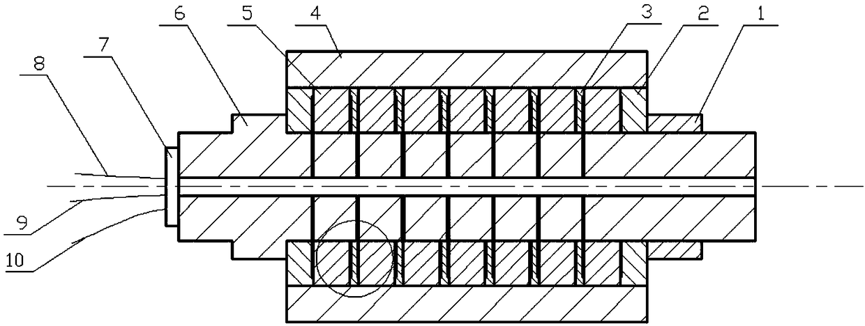
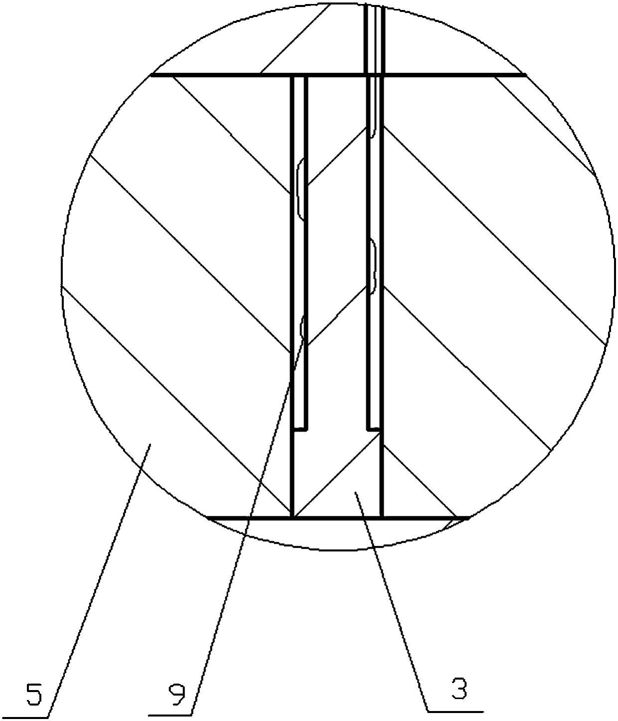
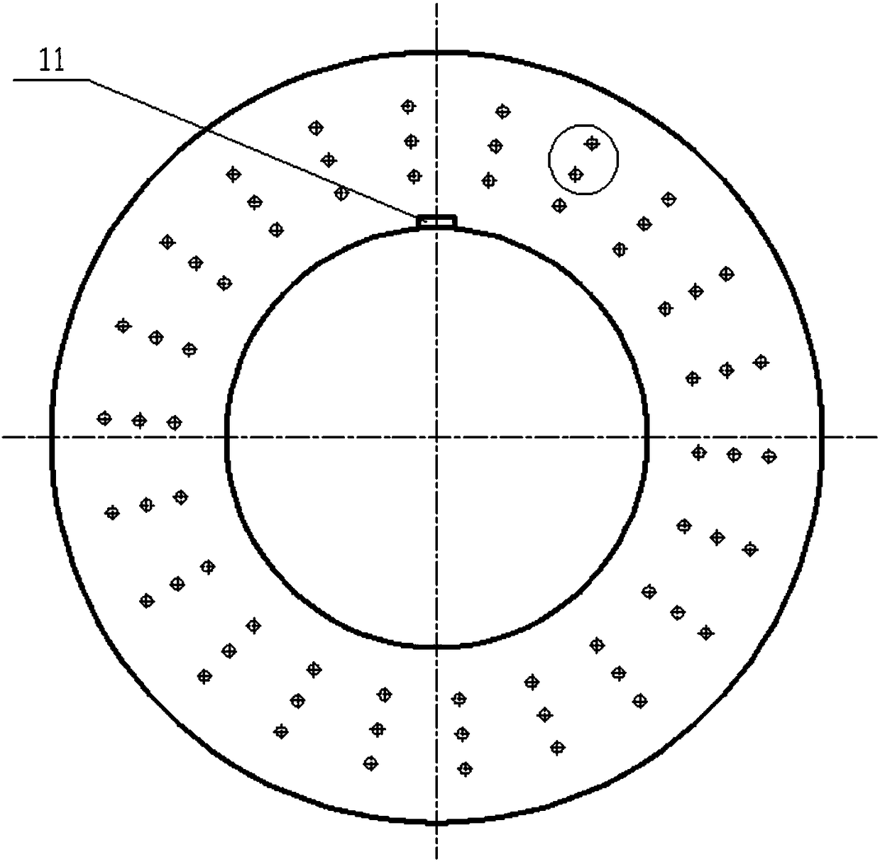
[0024] exist figure 1 In the schematic diagram of the front section of the segmented flexible roll crown control roll shown in the figure, the roll core 6 is a cylindrical forged steel metal rod with an axial center through hole inside the roll core and an annular boss on the outer side of the roll core. , the other side is provided with an external thread, and there are 7 parallel annular electromagnetic rods 5 on the non-bossed platform of the roller core. Regularly arranged axial through holes, such as image 3 As shown, there is a bundle of wires passing through these "honeycomb"-shaped vias, such as Figure 4 As shown, the winding method starts from the radially innermost circle to the outermost circle, and then winds circle by circle, and finally winds from the innermost circle again, passes throu...


PUM


Abstract

The invention discloses a sectionalized flexible roll convexity regulation and control roller. The sectionalized flexible roll convexity regulation and control roller is mainly characterized in that an axial center through hole is formed in a roll core, one or a plurality of parallel ring-shaped electromagnetic rods are arranged on the roll core, axial through holes are regularly formed in the ring-shaped electromagnetic rods to be similar to 'honeycombs' in the appearance, a bundle of wires penetrates each axial through hole, two ends of each bundle of wires are individually connected with power sources by slide rings, signals can be independently fed by each bundle of wires, a groove is formed in the inner peripheral surface of each electromagnetic rod, a temperature sensor is arranged in each groove, an insulating support ring is arranged between every two corresponding electromagnetic rods, grooves are formed in two end surfaces of each insulating support ring, two shaft sleeve endcovers are arranged on the outer sides of the electromagnetic rods at two ends of the roll core, one of the shaft sleeve end covers is positioned by shaft shoulders, the other shaft sleeve end coveris connected onto the roll core in a threaded manner, grooves are formed in the end surfaces, which are adjacent to the corresponding electromagnetic rods, of the two shaft sleeve end covers, cylindrical roll sleeves are arranged on the outer peripheral surfaces of the electromagnetic rods, the insulating support rings and the shaft sleeve end covers, and a slide ring is arranged on the top of theend, which is provided with a boss, of the roll core. The sectionalized flexible roll convexity regulation and control roller has the advantages of high plate shape regulation and control ability, roller stiffness and regulation and control speed.

Description

technical field [0001] The invention relates to a steel rolling equipment in the metallurgical industry, in particular to a roll. Background technique [0002] Shape control technology is one of the core technologies of the strip rolling process. Especially with the rapid development of the processing and manufacturing industry, users have put forward higher requirements for the geometry and size of the rolled strip, which further highlights the importance of shape control. importance. Under the condition that the existing rolling mill models are relatively stable, the roll shape becomes the most direct and active factor in controlling the shape of the strip. The shape control technologies that have been applied in the industry mainly include hydraulic bending rolls, CVC series technology, VC rolls, DSR rolls, etc. Hydraulic roll bending technology uses hydraulic pressure to bend the roll to control the crown, which belongs to directly changing the roll crown. The CVC tec...

Claims


Application Information

Patent Timeline
IPC IPC(8): B21B27/03B21B27/08
Inventor 杜凤山杨庭松刘文文冯岩峰孙明翰许志强孙静娜
Owner YANSHAN UNIV
Why Eureka
Eureka Blog
Learn More