Eureka AIR delivers breakthrough ideas for toughest innovation challenges, trusted by R&D personnel around the world.

Solid plate cutting device

A technology of cutting device and solid plate, applied in metal processing, removing smoke and dust, cleaning methods and utensils, etc., can solve problems such as endangering the health of operators, inability to make better use of residual materials, affecting the cleanliness of the production environment, etc. The effect of cutting speed and quality, small cutting seam, and avoiding flying around

Pending Publication Date: 2018-08-07
黄 志力
View PDF5 Cites 4 Cited by
  • Summary
  • Abstract
  • Description
  • Claims
  • Application Information

AI Technical Summary

Problems solved by technology

[0002] During the production and processing of plates, it is often necessary to cut out the corresponding circular cake-shaped materials on the entire solid plate. Since the entire plate area is relatively large and the thickness is relatively thick, cutting is relatively laborious and lacks a good Processing equipment, the manufacturer usually cuts the whole plate into square blanks slightly larger than the round cake material, and then grinds the square blank into a round cake shape. This method is less efficient, and the square blank The four corners of the material cannot be reused after being ground and removed, resulting in the inability to make better use of the remaining material
And the traditional cutting and grinding process will produce a lot of waste, scattered and falling in the working environment, which not only affects the cleanliness of the production environment, but also endangers the health of the operators

Method used


Image

  • Solid plate cutting device
  • Solid plate cutting device

Examples


Embodiment Construction

[0016] In order to make the object, technical solution and advantages of the present invention clearer, the present invention will be further described in detail below with reference to the accompanying drawings and embodiments. However, it should be understood that the specific embodiments described here are only used to explain the present invention, and are not intended to limit the scope of the present invention. Also, in the following description, descriptions of well-known structures and techniques are omitted to avoid unnecessarily obscuring the concept of the present invention.

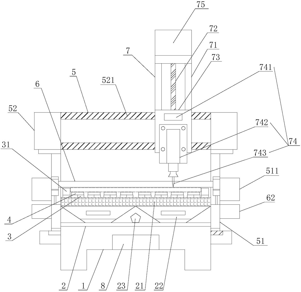
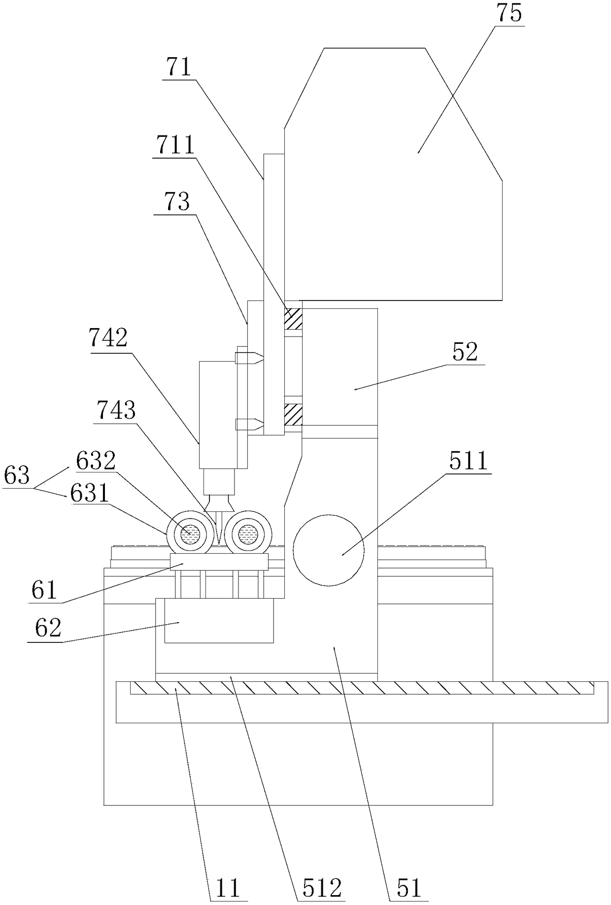
[0017] refer to figure 1 and figure 2 , the embodiment of the present invention provides a solid plate cutting device, including a base 1, a dust suction mechanism 2, a cutting pad 3, a cutting pad 4, a first positioning mechanism 5, a second positioning mechanism 6, a cutting mechanism 7 and a control Mechanism 8, above the base 1 is provided with a dust suction mechanism 2, above the desc...


PUM


Abstract

The invention discloses a solid plate cutting device. The device includes a base, a dust suction mechanism, a cutting padding block, a cutting padding plate, a first positioning mechanism, a second positioning mechanism, a cutting mechanism and a control mechanism; the dust suction mechanism is arranged above the base, the first positioning mechanism includes a sliding base and a cutting mechanismmounting plate, and the cutting mechanism is mounted on the cutting mechanism mounting plate and consists of a base plate, a retractable rod, a fixing plate and a cutting head. The first positioningmechanism and the second positioning mechanism cooperate with each other under driving of a servo motor, positioning is precise, and a cutter of the cutting mechanism cuts a solid plate between two parallel roller shafts; the needle-shaped cutter is driven by the two roller shafts to conduct circular motion for cutting, cutting seams of the cutter are small, the cutting dimension is accurate, thecutting speed is increased, the cutting quality is improved, and the utilization rate of materials is high. Waste shreds generated during cutting are sucked into a dust storage box below through a dust suction port and are prevented from scattering all around, and therefore the solid plate cutting device is environmentally friendly.

Description

【Technical field】 [0001] The invention relates to the technical field of solid plate processing, in particular to a solid plate cutting device. 【Background technique】 [0002] During the production and processing of plates, it is often necessary to cut out the corresponding circular cake-shaped materials on the entire solid plate. Since the entire plate area is relatively large and the thickness is relatively thick, cutting is relatively laborious and lacks a good Processing equipment, the manufacturer usually cuts the whole plate into square blanks slightly larger than the round cake material, and then grinds the square blank into a round cake shape. This method is less efficient, and the square blank The four corner materials in the material cannot be reused after being ground and removed, resulting in the inability to make better use of the remaining materials. Moreover, a lot of waste chips are generated during the traditional cutting and grinding process, which are sca...

Claims


Application Information

Patent Timeline
Patent Type & Authority Applications(China)
IPC IPC(8): B26D1/45B26D5/06B26D7/00B08B15/04
CPCB08B15/04B26D1/45B26D5/06B26D7/00B26D7/0006
Inventor 黄志力
Owner 黄 志力
Why Eureka
Eureka Blog
Learn More