Device and method for automatic balancing for unbalance faults of large rigid rotor

A rigid rotor, balance failure technology, applied in measurement devices, static/dynamic balance tests, instruments, etc., can solve the problems of ineffective real-time rotor, balance, etc., achieve precise position control, avoid the falling of the car, and achieve position control Effect

Pending Publication Date: 2018-08-07
ANHUI UNIVERSITY OF TECHNOLOGY
View PDF8 Cites 11 Cited by
  • Summary
  • Abstract
  • Description
  • Claims
  • Application Information

AI Technical Summary

Problems solved by technology

[0008] The purpose of the present invention is to overcome the deficiency that the rotor cannot be effectively balanced in real time in the prior art, and to provide an automatic balancing device and method for unbalanced faults of large rigid rotors

Method used


Image

  • Device and method for automatic balancing for unbalance faults of large rigid rotor
  • Device and method for automatic balancing for unbalance faults of large rigid rotor
  • Device and method for automatic balancing for unbalance faults of large rigid rotor

Examples


Embodiment 1

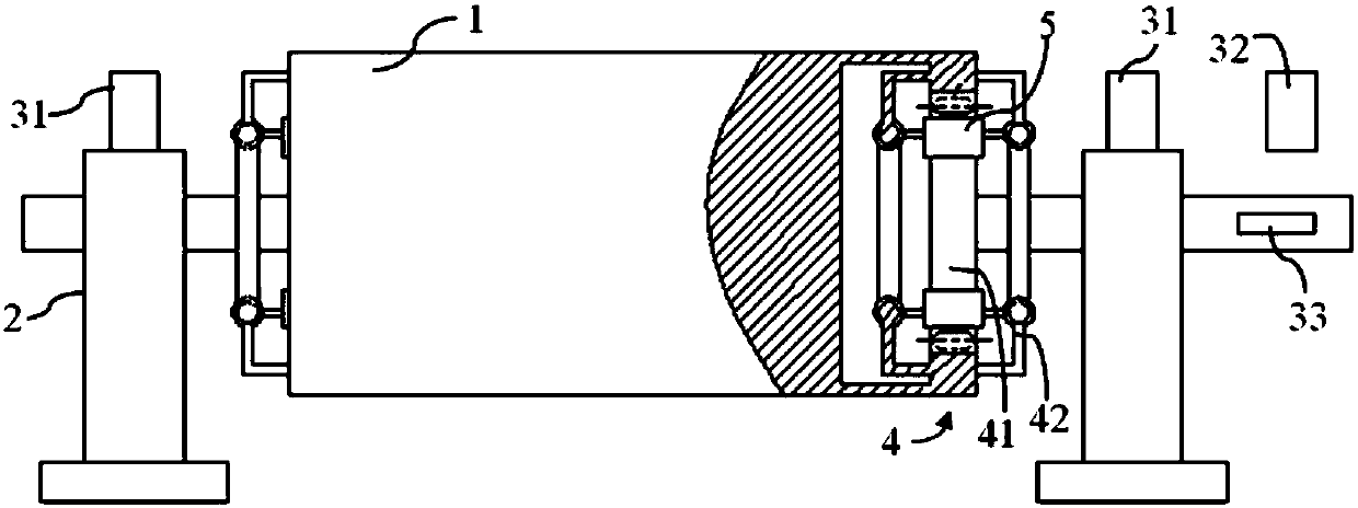
[0043] combine Figure 1 ~ Figure 3 , a large-scale rigid rotor unbalance fault automatic balancing device in this embodiment includes a rotor 1 installed between two bearing brackets 2, and track mechanisms 4 respectively arranged on the vertical surfaces at both ends of the rotor 1.

[0044] The two bearing brackets 2 are symmetrically arranged to carry the rotor 1. The rotor 1 can be driven by a structure such as a motor. The specific driving form is selected according to the actual use, and this embodiment does not make specific requirements.

[0045]This embodiment is to dynamically balance the rotor 1 on both sides, including the track mechanism 4 arranged on the vertical surfaces at both ends of the rotor 1. The track mechanism 4 is arranged in a circular shape and must be coaxial with the rotor 1 to ensure that it can be used in the later stage. Provide an exact location.

[0046] The track mechanism 4 is vertically arranged to ensure that the counterweight trolley th...

Embodiment 2

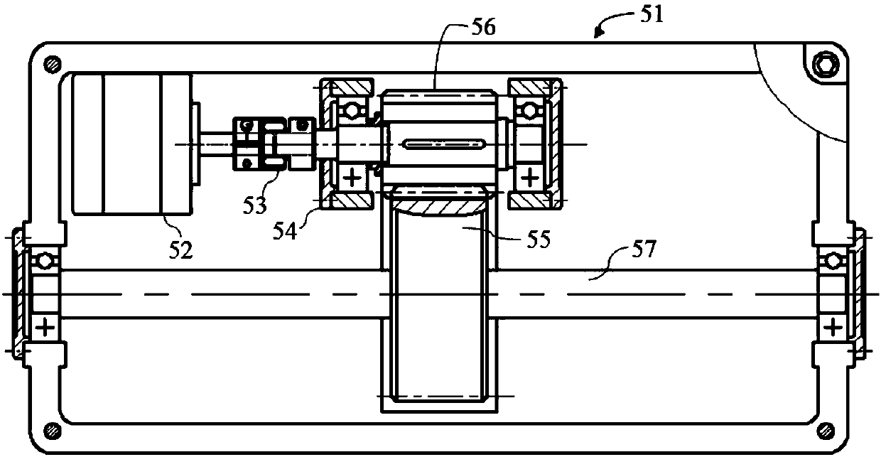
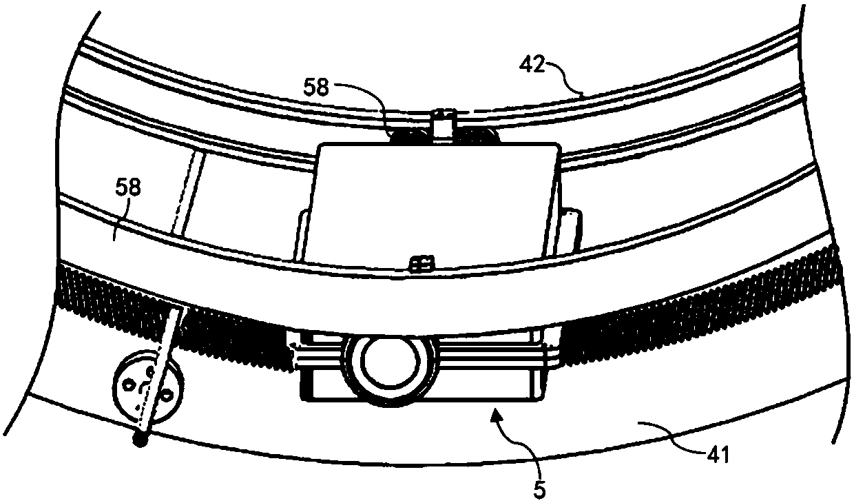
[0056] combine figure 2 , a large-scale rigid rotor unbalance fault automatic balancing device of the present embodiment, as a structural form of the counterweight trolley 5, it includes a driving power supply, a trolley housing 51, a travel gear 55 and a motor 52, and the travel gear 55 passes through the rotating shaft 57 is connected with the bearing at two ends of the trolley housing 51, and can rotate freely. The driving power supplies power to the motor 52 to drive the travel gear 55 to rotate. Since the travel gear 55 cooperates with the internal teeth of the track ring gear 41, the motion accuracy can be guaranteed.

[0057] Motor 52 is a stepper motor, in order to drive counterweight trolley 5 motions, it has multiple driving modes. For example, a pulley is connected to the rotating shaft of the motor 52, and the corresponding pulley is configured on the rotating shaft 57. The two pulleys are connected by a transmission belt, so that the driving force of the motor c...

Embodiment 3

[0061] In this embodiment, a structure in which the counterweight trolley 5 is driven is preferred. In this embodiment, a transmission gear 56 is connected to the rotating shaft of the motor 52 , and the transmission gear 56 meshes with the travel gear 55 .

[0062] A pair of bearing housings 54 are fixed on the trolley housing 51 , and the central axis of the transmission gear 56 is mounted on the bearing housings 54 . In this embodiment, a shaft coupling 53 is provided on the rotating shaft of the motor 52 , and the other end of the shaft coupling 53 is connected to the central shaft of the transmission gear 56 .

[0063] Because the traveling gear 55 meshes with the track ring gear 41 and the transmission gear 56 at the same time, when the stepper motor drives the transmission gear 56 to rotate, the travel gear 55 rotates, and then the counterweight trolley 5 can move in the track ring gear 41 .

[0064] Through gear transmission, compared with chain wheel and pulley transm...


PUM


Abstract

The invention discloses a device and a method for automatic balancing for unbalance faults of a large rigid rotor, and belongs to the field of rotor balancing. The device for automatic balancing comprises a rotor and track mechanisms, wherein the rotor is arranged between two bearing brackets; the track mechanisms are respectively arranged at the vertical surfaces of both ends of the rotor; two counterweight trolleys are arranged in each track mechanism; a motor in each counterweight trolley is used for driving the corresponding counterweight trolley to rotate along the corresponding track mechanism; a vibration signal and a rotation speed signal detected by a sensor are transferred to a balance tester; the processed signals are transferred to a control system in each counterweight trolleyby a signal generator; the control system is used for sending a pulse signal to each motor, so as to control each counterweight trolley to move in the corresponding track mechanism. The device has the advantages that by arranging a vertical circular track for moving each counterweight trolley, the position of a balance block can be automatically obtained according to the fault conditions, and theautomatic balancing can be realized in the running process of the rotor; the time is shortened, and the benefit is improved.

Description

technical field [0001] The invention relates to the technical field of rotor balancing, in particular to an automatic balancing device and method for unbalanced faults of large rigid rotors. Background technique [0002] In the rotating mechanical system, the rotor is an important part, and the vibration caused by the unbalanced rotor is the main cause of vibration, noise and mechanism damage of mechanical equipment. Among all mechanical failures, the failure caused by rotor unbalance accounts for about 60%. Therefore, in order to reduce mechanical failures and ensure its safe and stable operation, it is of great significance to perform dynamic balance testing and calibration of rotating machinery rotors. The dynamic balancing methods mainly include the balancing machine method and the on-site dynamic balancing method. On-site dynamic balancing method has been widely used for its advantages of convenient use, low price and high efficiency. [0003] At present, the method ...

Claims


Application Information

Patent Timeline
Patent Type & Authority Applications(China)
IPC IPC(8): G01M1/38
CPCG01M1/36
Inventor 孟瑞谢能刚王璐舒军勇
Owner ANHUI UNIVERSITY OF TECHNOLOGY
Why Eureka
Try Eureka